MG 615. Service Manual - part 3
 

  Index      Manuals     MG 615. Service Manual


Search            copyright infringement  


Content      ..     1      2      3      4      ..


MG 615. Service Manual - part 3


INSTRUMENTS AND CONTROLS

information in ‘Locking the Car and Arming the Alarm’ in
‘Starting & Driving’.

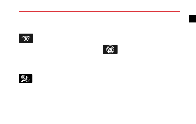
Glow Plug Warning - Yellow

The warning light illuminates yellow. The glow plug warning
is used to indicate to the driver that the diesel engine
glow plugs are still heating and are below their cut-off
temperature threshold, above which the engine may be
cranked.

Passenger Airbag Off - Yellow

The warning light is located on the remote display module
and is used to indicate that the passenger airbag has been
disabled. If the passenger airbag has been disabled, the
light will remain illuminated until the airbag is enabled,
and the message

Passenger Airbag Off

will appear

in the message centre. Once the passenger airbag has
been enabled, the light will extinguish and the message

Passenger Airbag On

will appear in the message

centre.

Note: The remote display module is mounted on the
roof.

Passenger Airbag On - Yellow

The warning light is located on the remote display module
and is used to indicate that the passenger airbag has been
enabled. If the passenger airbag has been enabled, the
light will remain illuminated until the airbag is disabled,
and the message

Passenger Airbag On

will appear

in the message centre. Once the passenger airbag has
been disabled, the light will extinguish and the message

Passenger Airbag Off

will appear in the message

centre.

Note: The remote display module is mounted on the
roof.

33

1

-------------------------------------------------------------------------------------------------------------------------------------------------------------

INSTRUMENTS AND CONTROLS

Lighting Switch

Master Lighting Switch

1

2

3

A U T O

0

1

1 AUTO lights

*

2 Side, tail and licence plate lights

3 Headlights

AUTO Lights

*

With the ignition switched on, turn the master lighting
switch to AUTO position (1).

The AUTO lighting

system constantly monitors the ambient light levels and
automatically switches the dipped headlamps, side light,
tail lights on and off as required.

Side, Tail and Licence Plate Lights

Turn the master lighting switch to position (2), to switch on
the side, tail and licence plate lights. The sidelight warning
light will illuminate and Sidelights On will appear in the
message centre. If the lights are still switched on when the
ignition handset is removed and the driver’s door is opened,
an audible warning will be given and Lights On information
will be displayed in the message centre.

Headlights

With the ignition switched on, turn the master lighting
switch to position (3), to switch on the headlights.

34

-------------------------------------------------------------------------------------------------------------------------------------------------------------

INSTRUMENTS AND CONTROLS

Headlight Courtesy Delay

Having stopped the car and turn the ignition off. Then
move the direction indicator lever to the main beam
position.

The headlights and rear fog guard lights will

remain illuminated for you setting. For information on
configuring the Lights Off Delay, see ‘Menu’of ‘Message
Centre’.

Daytime Running Lights

The daytime running lights turn on automatically when
the ignition switch is in position II. When the side or
headlights are switched on, the daytime running lights are
extinguished.

Instrument Dimmer Control

A U T O

When the ignition is in position II, and the sidelamps
or dipped headlamps are on, rotate the control up to
increase or down to decrease instrument illumination. The
instrument dimmer also controls the backlight illumination
of switches, audio system, message centre and the satellite
navigation system (if fitted).

When the sidelights are

switched on the message centre display on the instrument
pack and the satellite navigation system (if fitted) will dim
automatically.

Manual Adjustment Headlight Levelling

*

A U T O

The angle of the dipped beam is affected by the distribution
of passenger and luggage weight within the car.

To ensure correct headlamp aim, and not dazzle on-coming
traffic, the headlamp levelling switch position should be

35

1

-------------------------------------------------------------------------------------------------------------------------------------------------------------

INSTRUMENTS AND CONTROLS

adjusted according to the vehicle loading condition in
accordance with the following table:

Position

Load

0

Driver, or driver & front passenger

1

All the seats occupied with no load

2

All the seats occupied plus an evenly
distributed load in the boot, achieve the gross
vehicle weight

3

Driver only, plus an evenly distributed load in
the boot, achieve the gross vehicle weight

Dynamic Headlamp Levelling

*

Dynamic Headlamp Levelling is part of the Adaptive
Frontlighting System (AFS). With the dipped beam
headlamps switched on, vehicles fitted with the Dynamic
Headlamp Levelling system will automatically adjust the
headlamp aim according to vehicle speed, acceleration,
deceleration and uneven road surfaces.

Cornering Lamps

*

Cornering Lamps are part of the Adaptive Frontlighting
System (AFS). Illumination of driver blind spots when
cornering is achieved by adding extra lights to the
traditional headlamps.

When travelling forwards, the dipped headlamps are
switched on, vehicle speed is below 25 mph (40 kph) and
the steering wheel is rotated in excess of 30 degrees, the
corresponding cornering lamp will illuminate. If reversing,
the cornering lamp opposite the steering wheel rotational
direction will illuminate.

For AFS configuration please

refer to 'Message Centre' in the 'Instrument and Controls'
section.

36

-------------------------------------------------------------------------------------------------------------------------------------------------------------

INSTRUMENTS AND CONTROLS

Fog Lights

Fog lights should only be used in poor
visibility, inappropriate use could dazzle
other drivers.

Note:

The

rear

fog

lights

are

switched

off

automatically when the main lighting switch is turned
off.

Rear Fog Lights

When the ignition is in position II, lights are switched on,
pull the light switch out to position 1 to switch on the rear
fog lights. The warning light in the instrument pack will
illuminate when the fog lights are on. Rear Fog Lamps On
will appear in the message centre.

37

1

-------------------------------------------------------------------------------------------------------------------------------------------------------------

INSTRUMENTS AND CONTROLS

Direction Indicator/Main Beam Lever

Take care not to dazzle oncoming vehicles
when driving using main beam headlights.

2

3

1

4

Direction Indicators

Move the lever down (1) to indicate a LEFT turn, or up
(2) to indicate a RIGHT turn. The corresponding GREEN
warning light in the instrument pack will flash in time with
the direction indicators.

To indicate a lane change, press the lever briefly and
release, the indicators will flash three times and then
cancel.

Headlight Main and Dipped Beam

When the ignition is in position II, dipped headlamps
switched on, push the lever away from the steering wheel
(3) to switch on main beam. The BLUE warning light in
the instrument pack illuminates, Main Beam On appears in
the message centre. Push the lever away from the steering
wheel (3) again to switch off Main Beam headlamp.

Headlight Flash

To briefly flash the main beam on and off, pull the lever
towards the steering wheel (4) and then release.

38

-------------------------------------------------------------------------------------------------------------------------------------------------------------

INSTRUMENTS AND CONTROLS

Lamp Failure

Failure of any of the following bulbs will be confirmed by a
message and symbol in the message centre.

• Front direction indicator.

• Rear direction indicator.

• Dipped beam headlamps.

Note: The side lamps, side repeater lamps and centre
high mounted stop lamp are not monitored by this
system.

Hazard Warning Lights

Press the switch to operate the hazard warning lights. All
the direction indicators and direction indicator warning
lights will flash together. Press again to switch off and the
direction indicators and direction indicator warning lights
will turn off.

39

1

-------------------------------------------------------------------------------------------------------------------------------------------------------------

INSTRUMENTS AND CONTROLS

Wipers and Washers

IMPORTANT

• Avoid operating the wipers on a dry screen.

• In freezing or very hot conditions, ensure that the

blades are not frozen or stuck to the glass before
being operated.

• In winter, remove snow or ice from around the arms

and blades, including the wiped area of the screen.

Front Windscreen Wiper Controls

1

6

5

2

3

4

The wipers and washers will operate with the ignition in
position Ⅰ, i.e.

Auxiliary.

Push the lever up to select

different wiper speeds.

• Intermittent wipe/Automatic wipe

*

(1)

• Normal speed wipe (2)

• Fast speed wipe (3)

40

-------------------------------------------------------------------------------------------------------------------------------------------------------------

INSTRUMENTS AND CONTROLS

• Single Wipe (4)

• Wiper Delay Switch (5)

• Programmed Wash/Wipe (6)

Intermittent wipe/Automatic wipe

*

Push the lever (1) up to select the intermittent
wipe/Automatic wipe

*

, wipers will wipe automatically.

Rotate the switch (5) to vary the intermittent time of
wiper operation. Intermittent operation time of wipers
will also be amended according to road speed - increased
road speed will reduce intermittent operation time.

Normal Speed Wipe

Push the lever (2) up to select the normal speed wipe,
wipers will wipe at normal speed. If the road speed drops
below 8 km/h while the wipers are operating, they will
slow to the next slowest operating mode; i.e. fast wipe
to normal wipe, normal wipe to intermittent. This facility
can be manually overridden by changing the wipe setting.

Fast Speed Wipe

Push the lever (3) up to select the fast speed wipe, wipers
will wipe at high speed. If the road speed drops below 8
km/h while the wipers are operating, they will slow to the
next slowest operating mode; i.e. fast wipe to normal wipe,
normal wipe to intermittent. This facility can be manually
overridden by changing the wipe setting.

Single Wipe

Pull the lever (4) down and release, wipers will wipe once.
If the lever is held down, the wipers will operate at high
speed until the lever is released.

Programmed Wash Wipe

Pull the lever (6) towards the steering wheel - the washers
operate immediately. After a short delay, the wipers will
commence operating in conjunction with the washers,
both functions continuing until the lever is released. The
programmed wash wipe function can be disabled; refer to
section ‘Prog Wash Wipe’ of ‘Main Menu’ in the Chapter
‘Message Centre’.

41

1

-------------------------------------------------------------------------------------------------------------------------------------------------------------

INSTRUMENTS AND CONTROLS

IMPORTANT

If the washers fail to deliver the screen wash solution
(dirt or ice may have blocked the jets), release the
lever immediately. This will prevent the wipers from
operating, and the consequent risk of visibility being
impaired by dirt smearing across the unwashed
windscreen.

Headlamp Washers

*

Cars equipped with HID headlamps feature headlamp
washers, these are located in the bumper.

After switching on the headlamps, the first use of the
screenwashers will initiate a headlamp wash. After this,
every fourth screenwash will result in a single headlamp
wash.

Rain Sensor

*

Some models are equipped with a rain sensor fitted to
the inside of the windscreen behind the rear view mirror.
The sensor is able to detect varying amounts of water on
the outside of the windscreen. With the wiper control

set to intermittent, the variable delay will be adjusted
automatically according to the information supplied by the
rain sensor.

Note: If the sensor detects constant rain, the wipers
will operate continuously. The sensitivity of the sensor
can be altered by means of the wiper variable delay.

42

-------------------------------------------------------------------------------------------------------------------------------------------------------------

INSTRUMENTS AND CONTROLS

Steering Column

Steering Column Adjustment

Do not attempt to adjust the height or angle
of the steering wheel while the car is in
motion. This is extremely dangerous.

To adjust the angle and height of the steering column to
suit your driving position:

1 Fully release the locking lever.

2 Hold the steering wheel in both hands and tilt the

steering column up or down to move the wheel into
the most comfortable position.

3 Pull or push the steering wheel closer to, or further

away from your body.

4 Once a comfortable driving position has been selected,

pull the locking lever fully up to lock the steering
column into its new position.

43

1

-------------------------------------------------------------------------------------------------------------------------------------------------------------

INSTRUMENTS AND CONTROLS

Horn

When the ignition switch is in position I or II, press the
steering wheel pad where arrowed to operate the horn.

Note: The vehicle horn press and the driver's airbag
are located in close proximity on the steering wheel.
The illustration shows the position of the horn,

please ensure that you press in this area to avoid any
potential conflict with the operation of the airbag.

IMPORTANT

To avoid possible SRS issues, please do not press with
excessive force or hit the airbag cover when operating
the horn.

44

-------------------------------------------------------------------------------------------------------------------------------------------------------------

INSTRUMENTS AND CONTROLS

Mirrors

Exterior Mirrors

Note: Objects viewed in exterior mirrors may appear
further away than they actually are.

Mirror Glass Adjustment

L

R

2

1

1

• With the ignition in position I or II , press the

appropriate switch (1) to select the left or right mirror.
The selected (L) or (R) button will be illuminated.

• Use switch (2) to tilt the mirror glass up/down/left or

right.

• Use switch (1) again to disable the switch and prevent

inadvertently moving the mirror glass.

Heating Elements

*

The door mirrors have integral heating

elements which disperse ice or mist from the glass. The
heating elements operate while the Heated Rear Window
is switched on.

Note: The heated rear window and mirror heating
elements only work while the engine is running.

Mirror Folding

The body of each door mirror is designed to fold flat against
the side of the car on impact.

45

1

-------------------------------------------------------------------------------------------------------------------------------------------------------------

INSTRUMENTS AND CONTROLS

The mirrors can also be folded back manually towards the
side windows into a ‘park’ position to enable the car to
negotiate narrow openings, or when parked.

IMPORTANT

• The exterior mirror glass is electronically adjusted

using the mirror switch, DO NOT attempt to adjust
the mirror glass by hand, this could result in damage
to the adjustment components.

• Exterior mirrors are operated with motors.

Therefore, flushing with high pressure water jets
directly in the car wash may result in the failure of
the electric device.

46

-------------------------------------------------------------------------------------------------------------------------------------------------------------

INSTRUMENTS AND CONTROLS

Interior Rear-view Mirror

Before driving, adjust the body of the mirror by hand to
achieve the best possible view to the rear. The dipping
function of both the automatic and manual mirrors helps
to reduce glare from the headlights of following vehicles at
night.

Automatic Mirror

*

The interior mirror is equipped with a light sensor
(arrowed) which activates the automatic dipping function,
when a following vehicle’s headlights could dazzle the

driver. The automatic dipping function is inhibited when
reverse gear is selected.

Manual Mirror

*

Move the lever at the base of the mirror forward to ‘dip’
the mirror. Normal visibility is restored by pulling the lever
back again.

Note: In some circumstances, the view reflected in a
‘dipped’ manual mirror can confuse the driver as to
the precise location of following vehicles. Remember
to take additional care.

47

1

-------------------------------------------------------------------------------------------------------------------------------------------------------------

INSTRUMENTS AND CONTROLS

Vanity Mirror

The driver’s vanity mirror should only be
used when the car is stationary.

2

1

Pivot the sun visor (1) downward and open the cover to
use the vanity mirror (2).

48

-------------------------------------------------------------------------------------------------------------------------------------------------------------


Content      ..     1      2      3      4      ..