Tractors X60 Series. Manual - part 39
 

  Index      Tractors     Tractors X60 Series - service repair manual 2012 year


Search            


Content   ..  37  38  39  40   ..


Tractors X60 Series. Manual - part 39


155

Tyres, Wheels, Ballasting

6

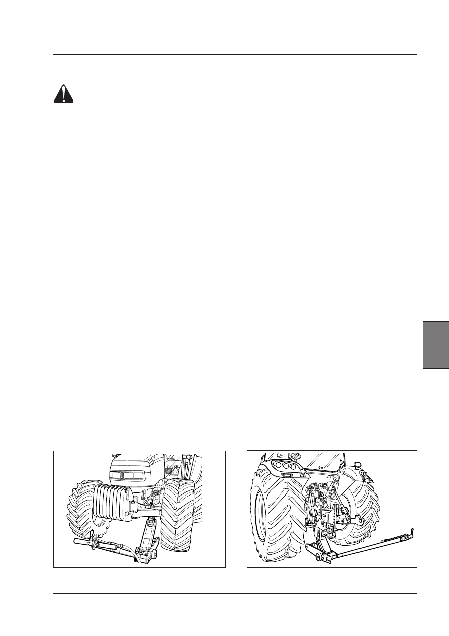
Fig. b

Fig. a

Wheel removing procedure

WARNING: If a wheel has to be removed (e.g. 
to  remove  a  punched  tyre),  this  operation 
must be carried out by a suitably equipped 
workshop. If the suitable equipment or such a 
workshop are not available, take the tractor 
to a specialised workshop, where the tractor 
will be lifted with an equipment suited to its 
weight and dimensions.

Procedure

- Turn off the engine, engage the parking brake and the
first gear. Engage the Park Lock (if equipped).
-  To  remove  a  front  wheel  apply  a  jack  lift  of  suitable
capacity at the front axle next to the wheel to be remove
(Fig. a).
- To remove a rear wheel, use wooden wedges on the front
axle to block completely any tractor swing. Use a jack lift
of suitable capacity in the centre of the rear axle (Fig. b).
- Loosen the nuts (bolts) fastening the wheel of about one
turn by the provided wrench.
- Before lifting the tractor, check there are no persons next
to it and do not touch the tractor again until it is not again
lowered to the ground.
- Lift the tractor a few centimetres.
- Unscrew all nuts (bolts) that fasten the wheel and re-
move the wheel
- Inflate the tyre if required. See the inflating procedure
in this chapter.
- Mount the wheel taking to exactly match the locating
pins. Screw the nuts (bolts) down again.
- Lower the tractor to the ground. Remove the jack and
fully tighten the nuts (bolts) alternating a nut (bolt) with
the opposite one.
-  As  soon  as  possible,  take  your  tractor  to  the  service
workshop  to  tighten  the  wheel  nuts  (bolts)  to  the  pre-
scribed torque.

156

Tyres, Wheels, Ballasting

Tyres - Front and rear tyre size combinations

The following is a list of tyre types and front/rear combinations. Please ask your Dealer for information on further com-
binations.

On tractors with 40 Kph overdrive gearbox only tures marked as «load index A8» may be used.

4WD tyre combinations

*

Only radial tyres

Tyre

Rim

Tyre

Rim

X60.20  X60.40  X60.50


X60.30

 420/70R 24 (130 A8)

W13-24

480/70R38 (145A8)

DWW15-38

X

X

X

 11.2R24(114 A8)

W10-24

16.9R30 (137A8)

DW14L-30

X

 12.4R24(119 A8)

W10-24

13.6R38 (128A8)

DWW12-38

X

X

X

 12.4R24(119 A8)

W10-24

18.4R30 (142A8)

DWW15-30

X

X

X

 13.6R24(121 A8)

W12-24

16.9R34(139 A8)

DWW15-34

X

X

X

 380/70R 24 (125 A8)

W12-24

480/70R34 (143A8)

W15L-34 PAVT

X

X

X

 440/65R24 (122 A8)

W13-24

540/65R34 (140A8)

DWW15-34

X

X

X  

 480/65R24(127 A8)

W13-24

600/65R34(145 A8)

DWW18L-34

X

X

X

 480/65R24(127 A8)

W13-24

540/65R38 (142 A8)

DWW15-38

X

X

X

 *14.9R24(126 A8)

W12-24

*18.4R34(144 A8)

W15L-34

X

X

 420/70R24(130 A8)

W13- 24

520/70R34(148 A8)

DWW15-34

X

X

 14.9R24(126 A8)

W12-24

16.9R38(141 A8)

DWW15-38

X

X

X

 320/70R24(116 A8)

W10-24

480/70R30 (141A8)

DWW15-30

X

380/85R24

W12-24

420/85R38

DWW15-38

X

 13.6R24(121 A8)

W12-24

13.6R38 (128A8)

DWW12-38

X

Front tyres 

Rear tyres 

Mod.

NOTE: Some of the tyre combinations considered here as acceptable MIGHT not be suited to all tractor models. To know 
the tyre combinations not listed here or for further information, see your dealer.

157

Tyres, Wheels, Ballasting

6

Adjusting the max. steering angle

The maximum steering angle of the 4WD front axle can
be varied depending on the type of tyre mounted and the
way the tractor is used. The angle is changed by adjusting
the stop screw (1) on the final drive of the axle.
This adjustment is very useful when adopting minimum
track since it prevents the wheels from interfering with
the engine housing.
The maximum steering angle is 55°.

Adjusting the steering angle.

1 - Adjuster screw.

2 - Check nut.

Hub cap stop.
1 - Stud.
2 - Adjuster screw.
3 - Lock nut.

Steering limit on front fender

To avoid the front fender clashing with the engine at the
max. steering angle, the hub cap rotation can be stopped
while leaving the kingpin free to reach the max. steering
angle.
Adjust the screw (2) so that it hits the bolt (1) before the
hub cap clashes with the engine.

158

Tyres, Wheels, Ballasting

Adjusting wheel track

4WD axle - Adjusting wheel track

The front track on 4WD tractors can be adjusted by chan-
ging the position of the hubs and central wheel discs as
shown in the table below.

Make sure that the wheel nuts are correctly tightened to
the prescribed torque wrench setting:
Disk to hub: 270 Nm
Rim to disk: 210 Nm

IMPORTANT: After removing and fitting the wheels back 
again, it is important to check the torques of all bolts by 
means of a torque wrench at the following intervals:
- First check after 10 work hours.
- Second check after 50 work hours.
- Third check and further checks every 500 work hours.

WARNING:  When  you  lift  up  the  tractor  to 
adjust the wheel tracks, follow the directions 
for lifting in the Safety Notes section.

WARNING:  Maximum attention must be used 
when dismounting the front wheels: because 
of their weight, a suitable hoist must be used 
to remove and handle the wheels.


Content   ..  37  38  39  40   ..