Tractors X60 Series. Manual - part 33
 

  Index      Tractors     Tractors X60 Series - service repair manual 2012 year


Search            


Content   ..  31  32  33  34   ..


Tractors X60 Series. Manual - part 33


133

Operation

5

Float Position

(if available)

To operate the remote hydraulics in a float condition,
turn the lock control (2) fully counterclockwise.

This will allow the control lever to go completely for-
ward into the float position.

The remote hydraulic control levers can be locked out
of the float position. When using equipment for work
where the float position is not wanted, turn the lock
control one position clockwise so that the control lever
cannot be moved into the float position.

NOTE: Single action cylinders can be operated in a float or 
no float position at the same time that the hitch is operated.

134

Operation

Operating Hydraulic Motors

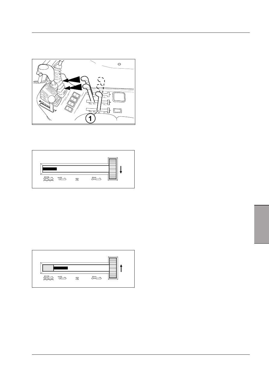
Connect hydraulic motors to the 1st remote circuit to
make sure of a constant flow of oil to the motor.

Stop the engine. Move remote control lever forward to
the float position.

Turn the locking control (1) fully anti-clockwise (three
positions from neutral), so that the movement of the
control lever is limited to two positions: retract and
float.

In this way the lever has only available the two posi-
tions to be used with hydraulic motors.

To engage the hydraulic motor, start the engine and
move the control lever forward from the float position
until against the lever lock. The hydraulic motor will
now operate.

To disengage the hydraulic motor, move the remote
control lever forward to the float position. Wait for the
hydraulic motor to slowly stop.

DO NOT DISENGAGE THE LEVER LOCK. Allowing the
control to return to the neutral position during motor
application will cause the motor to stop immediately.
This may cause damage to the hydraulic motor, hoses
and equipment.

To change the direction of rotation of the hydraulic
motor, change the hoses over on number 1 remote
coupler.

IMPORTANT:  To  avoid  damages  to  hydraulic  pumps  in 
tractors,  all  hydraulic  fluid  flowing  back  from  all  imple-
ments must be returned through the return circuit of the 
hydraulic motor.

Free discharge - Hydraulic Motor 
Return Circuit (if equipped)

The hydraulic motor return circuit can be used to
reduce restriction in the remote hydraulic motor return
line. This will result in more efficient hydraulic motor
operation.

To use the hydraulic motor return circuit, connect the
return line from the hydraulic motor or implement to the
connector (1).

135

Operation

5

Selecting the single/double acting 
modes

(Available only on some control valve types)

Some control valves can be regulated to control single-
acting cylinders.
To do this, just loosen the check nut (2 ) and turn the
screw fully anti-clockwise (1). Now lock the check nut
again.
To select the double-acting mode, turn the adjuster
screw (1) clockwise.

Flow divider (if installed)

On request, a flow divider is available (3) that is
mounted on the input plate of the control valve pack
and is coupled with the first auxiliary control valve, of a
type specific for operation with a flow divider.

Flow regulation

This device regulates the oil flow to the first control
valve, and is specially useful for those implements that
require a very limited oil flow to obtain precise move-
ments, or to regulate the speed in a hydraulic engine.
It also maintains an oil flow sufficient to use the lift
system and the external circuit at the same time, if only
the first auxiliary valve is used. To regulate the flow,
simply turn the control knob on the flow divider.

Quick couplings

Each control valve has two quick coupling female
half-connections of the “Push-Pull” (4) type that can be
connected to male half-couplings of any make so long
as they are of the same size. The half-coupling is very
simple to couple and uncouple: push to connect and
pull to detach.
Red - delivery/lifted
Yellow - return/lowered

WARNING: Remove any pressure from the 
circuit before hitching or unhitching the 
quick couplings.

Remove the dust cap. Clean the implement male cou-
pler before connecting.

Oil sump

Each quick coupling is connected to an oil sump (5) that
collects oil leaks due to hitching and unhitching of the
quick couplings. When the oil reaches the maximum level,
the sump should be emptied in collecting tanks so as not
to contaminate the environment.

IMPORTANT: DO NOT pour the reservoir contents back into 
the hydraulic system.  Dispose of contents in accordance 
with local regulations. DO NOT drain the contents on the 
ground or into a drain. Be responsible for the environment.

WARNING: When auxiliary control valves 
are used, their quick couplings can reach 
high temperatures. Therefore, safety glo-
ves suitable for such temperatures must be 
worn every time the connected implements 
are connected to or disconnected from the 
couplings.

IMPORTANT:  When  connecting  the  implement  hose  to 
the tractor, make sure the hose is long enough to permit 
the tractor to turn in both directions.

136

Operation

Engage the PTO as follows: 

OPERATION 1
Reduce the engine rpm.

OPERATION 2

To engage the PTO, release the switch (2) by pushing
the orange switch lock (1) down and at the same time
press the switch down (ON).

IMPORTANT: PTO will not engage if engine is started 

with the switch in the engage position.  Move switch to 
disengage and then engage. 

IMPORTANT: Never try to release dead locked im-

plements by repeated clutch engagement and disen-
gagement.  The front power takeoff clutch will slip and 
become damaged. 

Disengage the PTO as follows: 

OPERATION 1
Reduce the engine rpm.

OPERATION 2
Push the bottom of the switch (1) down to the OFF
position. The indicator lamp in the switch will go out
when the front power takeoff is disengaged.

OPERATION 3
When the engine is switched off the front power
takeoff is automatically disengaged. The indicator lamp
in the switch will go out to indicate the front PTO is
disengaged.

OPERATION 4
Always install the PTO shaft guard when the PTO is not
being used.

IMPORTANT: High-inertia implements do not become 

stationary immediately when PTO is disengaged.  Allow 
sufficient time for implement to “run down” to a halt 
before cleaning or adjusting.

The front power take-off has a 6 spline output shaft which
rotates  at  1000  rpm.    Engagement  is  electrohydraulic,
actuated by a three position rocker switch (OFF, ON and
ENGAGED) situated on the RH side console. Depending
upon market requirements, the front PTO can be supplied
with  two  different  directions  of  rotation  (clockwise  or
counter-clockwise).

IMPORTANT: When using implements that cause 

shock loads, always use a safety coupler between the 
implement and the PTO drive shaft. Before using the 
implement, check the correct operation both of the 
safety coupler and of the implement.

IMPORTANT: When using implements with quickly 

moving parts (such as mowers, reapers, snowploughs) 
ALWAYS fit an overrun device on the implement drive 
shaft, as a protection against possible PTO faults.

IMPORTANT: Ensure that the implement PTO shaft is 

not too long or the PTO is not damaged when the front 
mounted implement must be lifted fully up.

USE OF FRONT POWER TAKE-OFF

(if equipped)

DECAL

Provided by the front PTO maker. (If equipped with
front PTO).

WARNING: Keep yourself at a safe distance. Speed 
(rpm) and spinning of the front PTO shaft.

WARNING: Always mount the plastic guard 
on the PTO shaft when the PTO is not being 
used.


Content   ..  31  32  33  34   ..