Tractors X60 Series. Manual - part 32
 

  Index      Tractors     Tractors X60 Series - service repair manual 2012 year


Search            


Content   ..  30  31  32  33   ..


Tractors X60 Series. Manual - part 32


129

Operation

5

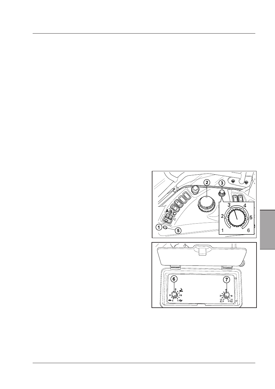
Operating the power lift

-  Select the power lift operating mode by means of the

mode selector (3).

 Position 1 -

Turn the knob anti-clockwise for
draft control mode. Use for plou-
ghing and similar operations that
require constant tractive force.

 Position 6 - 

Turn the knob clockwise


for position control mode. The


implement will remain at a con


stant height or depth.

 Intermed. positions  “Intermix” mode.
 (2  -  3  -  4  -  5)

Combining  position  control


and  draft  control;  for  use  on
variable soils or with subsoilers,
etc.

- Use the selector (6) to set a suitable descent speed

for the type of implement being used.

- Set the switch (1) to working position (A).
- Turn the control knob (2) to obtain the correct working

depth/height.

Working with tillage implements

-  If the implement pitches (makes large lifting and

lowering adjustments) in draft control mode, turn the
mode selector knob (3) clockwise to introduce an
element of position control (Intermix).

 The sensitivity of the electronic power lift to varia-

tions in the traction force required in working condi-
tions is automatically controlled and thus the opera-
tor need not intervene to make corrections.

Intermix/draft/position control 
adjustment

Tillage work: position 3 or 4.
Ploughing: positions 1 - 2 - 3 - 4.
Light soil turning: positions 4 - 5.
Grubbing: position 3 or 4.
Carried implement: position 6 (position control).

These settings are purely indicative and may vary de-
pending on the implement used and the soil.

Headland manoeuvres

-  Raise the implement at the end of the field by setting

the switch (1) to Pos. C. The arms lift to the height
set on the lift height limiter (7). Adjust the lift height
limiter so that if a drive shaft is connected between
the PTO and the implement, it is not twisted into
acute angles. This will also avoid wasting time lifting
the implement to transport height.

- To re-engage the implement, simply turn the switch

(1) to the working position (A). The implement will lo-
wer at the speed set with selector (7) until is reaches
the position selected with knob (2).

- To make the implement quickly re-engage the soil, press

the button (5).

130

Operation

Float mode

Used for implements that rest on the earth and follow
the relief of the ground.

-  Turn switch (1) to position (A).
-  Turn knob (2) to position (MAX), fully anti-clockwise as

far as it will go.

CAUTION:Comply with the maintenance and sa-
fety regulations governing the electrical system of 
the tractor to safeguard and protect the electronic 
power lift.

Transporting implements

-  Select the maximum transport height with the selec-

tor (7).

-  Raise the three-point linkage by turning the switch (1)

to Pos. C.

-  Set the selector (3) to position control mode (Pos. 6)

by turning it in an clockwise direction.

-  Set the down-speed selector (6) to position (1) (lock)

to prevent any accidental lowering movement should
the controls be accidentally operated.

WARNING: If the control lever (1) is moved 
to the links down position (A) and the work 
height control knob (2) is moved, the arms 
could be lowered. Set the lowering speed 
control (6) to Pos. 1 (lock) to prevent any 
accidental movement.

Shock absorber function in the 
transport position

This function is activated by moving the selector (1) up
(C) and pressing the button (4). Indicator light will come
on.

Press the button (4) again to deactivate the shock-ab-
sorber function in the transport position.

Electronic hitch error codes

In  case  of  electronic  hitch  malfunction,  the  instrument
cluster  will  display  an  exclamation  mark.  To  check  the
electronic hitch error code, refer to the Error menu EHr
on the digital instrument cluster.

WARNING: When an operation ERROR is displayed, 
ask the Dealer’s specialized personnel for help in-
dicating the error code. The Dealer’s personnel has 
specific competence to locate the error and the type 
of operation to be performed.

131

Operation

5

NOTE: To ensure that the hydraulic circuit operates in 

a regular way, the level of the transmission oil must be 
frequently checked and topped up if necessary, as indi-
cated in the “Checking the transmission oil level” part of 
the Maintenance section.

WARNING: Make sure that the hydraulic 
cylinders of the connected implements con-
tain the same type of oil as the transmission 
unit of the tractor to prevent this from being 
polluted and leading to faulty operation. 

WARNING: The tractor must only be started 
with the auxiliary valve levers are in neutral.

Control valve operation

-  Standard control valve.
 If set to positions A and B and released, the control

lever automatically returns to the hold position (N),
locking the implement in the position it has assumed.

-  Control valve with “kick-out” automatic release (op-

tional). If set to positions A and B, the control lever
remains blocked in the assumed position.

 Once the cylinder has reached end of stroke, the

pressure automatically releases the lever, setting it
back in the neutral position (N).

 The lever can be moved back to the neutral position

by hand before the cylinder reaches end of stroke.

-  Control valve with floating position (optional), used

for implements that normally rest on the ground and
follow its relief (e.g. graders, snow-ploughs, etc.). The
floating position is obtained by moving the lever (2)
to the second setting in position (F), where it remains
locked.

-  Specific control valve (optional) for use with hydraulic

motors.

NOTE: Do not use the control valve for hydraulic mo-

tors to supply single/double-acting cylinders to avoid any 
risks of accidents when using the connected hydraulic 
equipment.

Joystick (4) - It is coupled to two auxiliary control valves. If
shifted forward, it controls the 1st valve, if shifted laterally
it controls the 2nd valve. The lever can be locked by (5)
in three positions:
- Turned anti-clockwise and downward: Every move-

ment of the lever is locked in neutral.

-  Turned  clockwise  and  in  intermediate  position:  The

movement forward/back is allowed to control a single
control valve. To control the second control valve, the
locking device must be pulled up and the lever shifted
laterally.

-  Turned clockwise at the end of travel: The lever can

be moved in every direction and controls both valves.

AUXILIARY CONTROL VALVES

 [4.2.f]


Control valve levers operate the corresponding valve:
lever 1 operates valve number 1, lever 2 operates valve
number 2 and so on.

IMPORTANT: As the auxiliary control valves have differ-
ent configurations according to specific requirements 
of the user, please ask your Dealer for details about the 
proper and safe use of hydraulic equipment.

132

Operation

REMOTE HYDRAULICS OPERATION

There can be up to three remote control levers, each
having three or four positions (according to the type of
valve):

POSITION

FLOATING

RETRACT

NEUTRAL

EXTEND

The speed of movement of auxiliary equipment is deter-
mined by the distance the lever is moved from neutral
to the control position.

If the lever is moved fully rearward from neutral, the
equipment hydraulic cylinder(s) will extend quickly.
If the lever is moved rearward a short distance from
neutral, the equipment hydraulic cylinder(s) will extend
slowly.

If the lever is moved fully forward from neutral (when
float is locked out) the equipment hydraulic cylinder(s)
will retract quickly. If the lever is moved a short dis-
tance forward from neutral the equipment hydraulic
cylinder(s) will retract slowly.

NOTE: If there is too much restriction in the implement 
cylinders or other attachments, the restriction can cause 
a back pressure in the remote valve which will cause the 
remote lever on the console to return to neutral before the 
cylinder has reached full stroke. If the condition occurs, 
it will be necessary to manually hold the lever in position 
until the cylinder has reached full stroke. Continual use of 
the remote valve in this condition will cause the hydrau-
lic oil to over heat and possible damage to the hydraulic 
system.    If  the  condition  occurs  at  regular  intervals  the 
implement restriction should be corrected. It is normal for 
the control lever to return to neutral when the cylinders 
reach full stroke.

Neutral Lock

The remote hydraulic control levers can be locked in
the neutral position (1) to prevent moving the remote
valves. This can be done by moving the valve control le-
vers to the neutral position and turning the lock control
fully clockwise.

When used with equipment in the raised position, the
neutral lock provides a positive means of preventing the
accidental movement of the valve control levers.


Content   ..  30  31  32  33   ..