Tractors X60 Series. Manual - part 31
 

  Index      Tractors     Tractors X60 Series - service repair manual 2012 year


Search            


Content   ..  29  30  31  32   ..


Tractors X60 Series. Manual - part 31


125

Operation

5

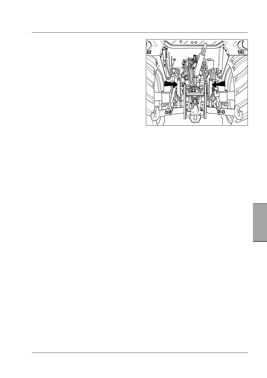
Supplementary cylinders.

Auxiliary cylinders

 [4.2.g]


The hydraulic hitch can be equipped (on request) with two
auxiliary cylinders, directly supplied by the hitch valve.

The lifting capacity with the auxiliary cylinders, diam. 60
mm (max. pressure 200 bar) is 5000 kg.

Contact your Dealer or area Agent to mount the auxiliary
cylinders and relative hydraulic fittings.

126

Operation

ELECTRONICALLY CONTROLLED 

HYDRAULIC POWER LIFT

Description

The electronically controlled hydraulic power lift is avai-
lable as an option on certain tractor models, depending
on the requirements of the particular market.

Electronic control of the power lift gives a number
of major benefits. In particular, control and response
signals can be processed and action taken to adjust for
variations in ground conditions encountered by the im-
plement in a fraction of the time possible with manual
controls.

To obtain the best results from the electronic control
system, you must be fully familiar with the controls on
the power lift control panel. A full description is given
below.

Power lift control panel

1 -  3-position up/down switch.

A: Lowering - Work position. This depends on the

way the controls (3 and 2) are regulated.

B: Stop - The lift arms are unable to move in any

way in the stop position.

C: Lifting - Transport: the fully raised position is

established by the limiter (7).

2 - Implement work depth/height control:

0 - Maximum depth.

10 - Max. height from ground.

3 -  Function selector:

-  Position Control, turned clockwise.
-  Draft Control, turned anti-clockwise.
-  Intermediate position: mixed Draft and Position

Control (INTERMIX).

4 -  Transport shock absorber engaged button and

indicator light

5 - Quick soil engagement button.
6 -  Down speed selector:

0 - Does not lower. Lock - Turned in anticlockwise
direction.

7 -  Maximum height limiter:

Minimum height: turned anti-clockwise.

Maximum height: turned clockwise.

- External power lift controls - Buttons on the fenders:

8 - up; 9 - down.

8-up

9-down

127

Operation

5

8-up 9-down

USE OF THE ELECTRONIC POWER 

LIFT

Enabling the power lift

The power lift incorporates a safety device which disa-
bles the hydraulic power lift controls when the engine
is off or if the external controls have been used. This
prevents accidental movement of the lift arms and links
as a result of interference with the controls or settings
while the tractor was stopped. When the engine has
been started, or after the external controls have been
used, simply turn the control switch (1) to position C.

-  If the switch is already in Pos. C, turn the switch (1)

to Pos. A then back to Pos. C again.

-  If the switch (1) is not in Pos. C and the lift is lowered,

turn switch (1) to Pos. C.

WARNING: The lift arms will rise as soon as 
the control panel is enabled. Limit the max. 
lifting height with the control (7) before re-
activating the electronic power lift.
- If you need to stop lift movement imme-
diately, simply turn the switch (1) to Pos. B.
- Before you enable the power lift controls, 
check that the settings of controls (3 and 2) 
do not cause any dangerous movement of 
the implement.

NOTE: The electronic power lift control system also in-
corporates safety devices which disable the lift functions 
if any of the following faults are detected:
1 -  Insufficient battery power.
2 -  Short circuit in the power line.
3 -  Position-control circuit malfunction.
If the electronic power lift fails to operate correctly after 
the controls have been enabled as instructed above, 
have the circuits checked by your local dealer.

WARNING: External controls must be operated 
at a safe distance, standing on one side out-
side the tractor and out of the overall width of 
mudguards. It is expressly forbidden to ope-
rate the controls from the rear of the tractor 
or standing on the inner side of wheels.

 [4.2.b]

128

Operation

Hitching an implement

From the internal control panel

-  Turn the power lift control switch (1) to Pos. C to

enable the power-lift control panel.

-  Turn the control switch to the working position (A).

-  Turn the function selector (3) clockwise to select

position control mode.

-  Turn the knob (2) anti-clockwise to lower the arms.
 The arms-down indicator should light up.

-  Manoeuvre the tractor to the right position and hitch

the implement’s ball-ends on to the ends of the links.
Fit safety pins to secure the hitch.

 Hitch up the top link.

-  Turn knob (2) clockwise to raise the implement.
 The arms-up indicator should light up.

With the external control buttons (8 - 9)

There is no need to enable the power lift in order to use
the external control buttons (8 - 9).

To use the external controls, just press on the buttons
to raise or lower the lift arms. Now enable the power lift
control panel by means of the switch (1).

NOTE:
- Arm movement stops as soon as the buttons are rele-
ased.
- Descent speed is 30% slower than max. speed with 
the external controls. Down speed regulation remains 
disabled.
- To enable the control panel controls after the external 
ones have been used, release the safety device by set-
ting the switch (1) to Pos. C and then to working position 
A.

8-up

9-down

WARNING: External controls must be operated 
at a safe distance, standing on one side out-
side the tractor and out of the overall width of 
mudguards. It is expressly forbidden to ope-
rate the controls from the rear of the tractor 
or standing on the inner side of wheels.

 [4.2.b]


Content   ..  29  30  31  32   ..