Tractors X60 Series. Manual - part 30
 

  Index      Tractors     Tractors X60 Series - service repair manual 2012 year


Search            


Content   ..  28  29  30  31   ..


Tractors X60 Series. Manual - part 30


121

Operation

5

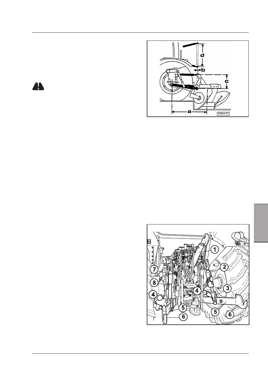
Implement hitch dimensions.
a - Horizontal distance between lower link pins of the

three-point hitch and the implement’s centre of
gravity.

 As small as possible (the greater is the weight of the

implement, the smaller it is).

b- Retraction of the third point: 0 to 80 mm (0 to 3.1 in.)
c- Height of top link hitch ball: 500-600 mm (19.7 to 23.6

in.)

d- Length of bar: 825+1.5 mm (32.5 in.)

NOTE: The plough shown in the figure is purely indi-
cative since the dimensions are valid for any type of 
implement.

Three point linkage

The three point linkage is used to connect the tractor to
implements controlled by the hydraulic lift.

The three-point linkage is suitable for connection to
implements of 2nd class as shown by the diagram and
data given in the figure.

WARNING: Always take great care when 
using or adjusting the three point linkage.

Hitching the implement

To allow the lift to operate in the correct way, you must
carefully check the dimensions of the implements to be
coupled to the tractor.

These couplings must be the same standard size as the
three point linkage of the tractor to prevent the whole
assembly from being subjected to irregular stress du-
ring work, caused by dimensional incompatibility. See
dimensions given in the figure.

Weight of the implement

To prevent the regular operation of the lifting system
from being impaired, the weight of the implements
must be less than the maximum load the lift can raise.
This value (given in the specifications) is only indicative,
since the distance at which the center of gravity of the
implement is set in relation to the three point linkage
can also exercise a notable influence.

If an implement, even when lighter than the indicated
weight, is set at an excessive distance from the tractor,
it will bear down on the three point linkage with a much
greater weight than the weight of the implement itself.

Three point linkage components

The articulated device with three point suspension
mainly consists of the following components:

1 -  Adjustable top link with length adjuster sleeve
2 -  Adjustable rh lift rod.
3 -  Rh rod adjustable fork
4 -  Lateral stabilizers (2 pcs).
5 -  Lower links.
6 -  Hitch couplings.
7 -  Lh rod adjustable fork.
8 -  Lh lift rod.

Mechanically adjusted three point linkage (Class 2).

122

Operation

Lower links

The lower links (4) transmit draft and support to the

implement. The lower links are available with fixed ball-

ends or with quick-hitch couplings (on request).

The tractor is supplied complete with Class 2 and 3

interchangeable ball ends to be installed on the imple-

ment hitch crossbar.

Quick hitch couplings

To hitch the implement, first pull the connecting cables
(1) from the driving seat to open the hitch lock (2).
Reverse the tractor towards the implement so that the
lower links are in the direction of the ball-ends fixed to
the crossbar of the implement.
Slowly raise the links of the power lift until the ball-ends
(C) automatically push against the spring-loaded quick-
hitch couplings (D) and are locked into place.
The hitch couplings can be opened driectly from the
cab by means of the control cables. RH adjustable rod.

Adjustable rh lift rod

The length of the rh adjustable lift rod (2) can be adju-
sted by means of the relative crank (1). This adjustment
is very useful since it levels the implement depending
on the type of work being carried out.

Turn the lever clockwise to shorten the rh vertical lift
rod.

Turn the lever anticlockwise to lengthen the rh vertical
lift rod.

On request the rh adjustable lift rod can be equipped
with a hydraulic jack (3), operated from the driving
seat, to adjust the cross angle of the implement.

Quick hitch couplings.
C - Quick hitch coupling.
D - Lock.
E - Control cable.

Rh lift road with hydraulic adjuster device (on request).

123

Operation

5

Vertical lift rods

The right and left vertical lift rods can be regulated by
means of an adjustment crank in order to alter the late-
ral angle of the implements. They can also be adjusted
by turning the backing plate through 90°: this gives
two settings, one with the plate fixed (A), the other with
the plate free to slide (B). This latter position must be
used for implements that require a certain freedom of
sideways movement (cultivators, spaders, harrows).

Fixed backing plate.

Free-sliding backing plate.

Backing plates for the hinge pins of the vertical rod forks.

Side stabilizers

The side stabilizers (1) can be set to reduce side swing
of the lower links of the three-point linkage.
When working with implements such as graders,
rollers, hoes, weeders, etc. the side swing of the lower
links can be adjusted according to the job on hand.
When working instead with ploughs, disk harrows, etc.
the stabilizers can be set to allow the lower links to
swing freely.

For the transport on road with lift links in high position,
lower links side swing must be restricted independently
of any previous adjustment during work.

Turn the stabilizers (2) for the adjustment:
–  turn anti-clockwise to increase side swing of three-

point linkage;

–  turn clockwise to reduce or even stop side swing of

three-point linkage.

If the three-point linkage is set on float mode, it is ne-
cessary to check that side swing is simmetrical on both
sides, taking the rear wheel rim as a reference.

Swing the three-point linkage all to the right and measu-
re the distance from lower link to wheel rim.

For special requirements, the link length can be so
adjusted as to offset the implement relatively to the
tractor axis. In this case the links must be adjusted to
different lengths, always assuring that the implement is
safely locked.

124

Operation

Adjustable top link (3rd point)

The adjustable top link (1) is connected to the tractor
through a bearing with two holes (2). The connection
hole should be selected according to the reaction to the
draft control.

Connection to the top hole gives a lower sensitivity, to
the bottom hole a higher sensitivity to the hitch draft
control.

The length of the link is varied so that the angle of the
implement can be regulated in relation to the ground.

During work, the top link should go slightly down
toward the tractor, when the lower links are parallel to
the ground.

For works in draft control mode, remember that it is
better to hitch the implement in the top hole if the
carried load is particularly heavy. This way a greater
uniformity of work is achieved.

On request, the adjustable top link is available with a
hydraulic device (1) to adjust the length of the link from
the driving place during work.

The top link has two holes for hitching the implement and
adjusting its slant.

Hitching the implement

1  -  Set the lift controls in position control mode..
2  -  Allow the three point linkage to descend.
3 - Adjust the top links to have maximum side play.
4  -  Back up the tractor.
5  -  Connect the coupling bar of the implement to the

ball-ends of the lower links and lock it in place with
the safety pins.

6  -  Adjust the length of the top links to give the imple-

ment freedom of sideways movement or lock it in
place according to the type of work required.

Releasing the implement

1  -  Lower the implement completely to the ground.
2  -  Shorten the side stabilizers to give maximum play

to the lower hitching links.

3  -  Remove the safety pins and release the coupling

bar.

Hydraulic adjustment of top link (3rd point) (on request).

Important recommendations when using and adjusting
the three point linkage.

WARNING:  before  any  adjustments  in  the 
three point linkage, the following operations 
are required: engage the first gear, engage the 
parking brake, turn the engine off and remove 
the ignition key.


WARNING:  Always  use  the  lift  in  position 
control mode when transporting implements 
hitched to the three point linkage.


WARNING: Always use the lift in position con-
trol mode when an implement is hitched or 
unhitched to or from the three point linkage.


WARNING: When the tractor is stopped, always 
lower any implements connected to the three 
point linkage.

 [4.2.c]

 
WARNING: Never work under an implement 
that is kept raised only by the hydraulic hitch, 
but always secure it with a suitable support. 
Engage  the  first  gear,  engage  the  parking 
brake,  turn  the  engine  off  and  remove  the 
ignition key.


Content   ..  28  29  30  31   ..