Tractors X60 Series. Manual - part 28
 

  Index      Tractors     Tractors X60 Series - service repair manual 2012 year


Search            


Content   ..  26  27  28  29   ..


Tractors X60 Series. Manual - part 28


113

Operation

5

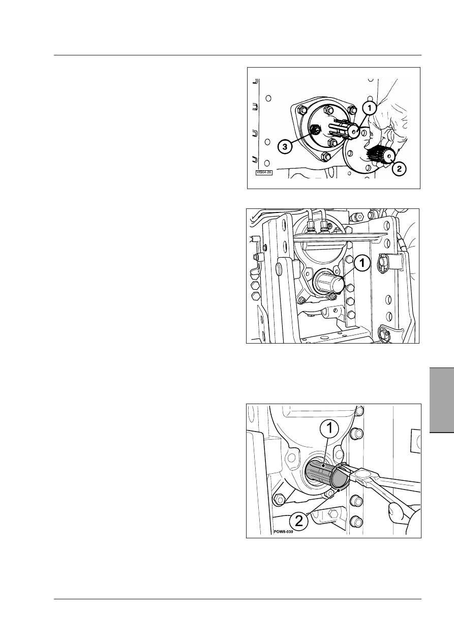
Interchangeable PTO shaft

Different PTO output shafts are available:

diameter 1 3/8” (34.9 mm.) shaft with 21 splines for

 1000 RPM power take-off, standard assembly (2).

diameter 1 3/8” (34.9 mm.) shaft with 6 splines for

 the 540 RPM PTO, provided with the tractor (1).

CAUTION: Only use the PTO driveline for 540 RPM if 
the implement used requires a power greater than 56 
kW (75 HP) since damages to the driveline itself and 
to the connected implements could injure bystanders. 
Implements requiring more than 56 kW (75 HP) may 
be  used  only  with  PTO  drivelines  at  1000  RPM,  21 
splines.

Proceed as follows to change the shaft:
• Remove the guard (4)
• Remove the four fixing bolts (3) and replace the ou-

tput shaft 1 or 2.

• Correctly tighten the for fixing bolts of the output

shaft (3).

• Mount the guard again (4).

After mounting the shaft, select the correct rotation
speed by means of the relative lever.

Replacing the interchangeable PTO shaft.

Changing the PTO driveline - NAO.
1 - PTO driveline. 2 - Spring ring.

North America

1000RPM PTO with 540RPM shaft, 6 splines. 

1000 RPM PTO only allowed with 1000 RPM 
shaft, 21 splines.

To change the output shaft (1), first remove the spring
ring (2) using suitable pliers.
Remove the shaft. Thoroughly grease the new shaft
and install it. Make sure that it has been completely
seated.
Fit the spring ring back in place and make sure that it
is positioned correctly: replace it if it is damaged or
deformed.
After mounting the required shaft, use the lever to
select the correct spinning speed.

WARNING: Do not use the 540RPM PTO driveline 
if the implement requires a power over 56 kW  (75 
HP). A damage to the shaft or the connected imple-
ment could be dangerous for nearby persons. Imple-
ments that require more than 56 kW (75 HP) should 
only be attached to the 1000 rpm PTO driveline, 21 
splines. 

114

Operation

PTO Safety Guards

 [4.2.e]

All tractors with a power take-off have a large safety guard
(1) and a small tube type guard (2) for the splined output
shaft. To prevent injury to the operator, the tractor power
take-off safety guard and the shields for the telescopic
shaft assembly must be used.
Keep the guards in place.

WARNING: Do not exceed the recommended 
speeds of the driven machine. Do not oper-
ate the PTO unless the shaft and drive line 
shields are in position and the tachometer is 
working correctly. Read and learn to under-
stand the Operator's Manuals supplied with 
any PTO driven equipment which may be 
attached to the machine.  

WARNING: Whenever a PTO driven imple-
ment is in operation, the PTO guards MUST 
be in place during operation to prevent 
injury to the operator or bystanders. Where 
attachments, such as pumps, are installed 
on the PTO shaft (especially if the tractor 
PTO guard is moved upward or removed) 
extended shielding equivalent to the PTO 
guard must be installed with the attach-
ment. Install the PTO guard again to its 
original position immediately after remov-
ing the attachment.  

WARNING: Never drive without the PTO caps 
(2) or protection (1) mounted. These com-
ponents protect the operators from injury 
and the shaft splines from damage.

PTO error codes 

In case of PTO malfunction, the instrument cluster will
display an exclamation mark. To check the PTO error code,
refer to the Error menu on the digital instrument cluster.

WARNING: When an operation ERROR is displayed, 
ask the Dealer's specialized personnel for help 
indicating the error code. The Dealer's personnel 
has specific competences to locate the error and the 
type of operation to be performed. 

115

Operation

5

Precautions when using the PTO

WARNING: PTO drivelines and implements 
operated by the PTO can be extremely dan-
gerous. It is important to comply with the 
following instructions:

WARNING: Before connecting, adjusting or 
working on implements operated by the 
PTO, disengage the PTO, stop the engine, 
remove the ignition key and engage the 
parking brake. Never work under raised 
implements.

WARNING: Make sure that all implements 
operated by the PTO are fitted with the 
correct protections, are in a good condition 
and comply with the laws in force.

WARNING: Before driving an implement 
through the PTO, ALWAYS make sure that 
all bystanders are well away from the trac-
tor.

WARNING: Fix the draw bar in the central 
position when using implements operated 
by the tractor’s PTO.

WARNING: When using the PTO with the 
tractor at a standstill, always make sure 
that the gears are in neutral position and 
that the parking brake is engaged.

WARNING: Before starting up any PTO-dri-
ven implement hitched to the three-point 
linkage, lift the implement to its full height 
and check that at least 1/4 of the total 
length of the telescopic section of the drive 
shaft is engaged. Adjust the height limiter 
on the electronic power lift to limit the 
maximum height of the stroke.

Paddy fields warning

When using the tractor in paddy fields or marshy 
ground, where the water level could rise above the 
height of the PTO, ask your dealer for instructions on 
all necessary waterproofing and sealing measures. If 
such measures are not taken, the guarantee could be 
rendered invalid.

IMPORTANT: When using implements that cause shock 

loads, always use a safety coupler between the implement 
and the PTO drive shaft. Before using the implement, check 
the correct operation both of the safety coupler and of the 
implement.

IMPORTANT: When using implements with quickly mo-

ving parts (such as mowers, reapers, snowplows) ALWAYS 
fit an overrun device on the implement drive shaft, as a 
protection against possible PTO faults.

IMPORTANT:  Ensure  that  the  implement  PTO  shaft  is 

not too long or the PTO is not damaged when the front 
mounted implement must be lifted fully up.

IMPORTANT: When using implements such as mowers, 

reapers, etc., check and clean every day the front grills, 
the cooling radiator, the transmission oil radiator and the 
air conditioning system radiator.


WARNING: High-inertia implements do not 
stop immediately after the independent PTO 
has been disengaged. Wait for the implement 
to slow down or stop completely before per-
forming any cleaning or adjustment opera-
tions.

WARNING:  Connect  the  implement  to  the 
tractor drawbar before connecting the imple-
ment  driveline  to  the  power  take-off.  When 
connecting  the  implement  driveline  to  the 
tractor, check the driveline for correct length, 
for  practicable  slant  and  for  free  telescopic 
movement. The correct length is important to 
prevent the driveline from hitting bottom or 
from separating in any tractor or implement 
operating position. An excessive slant could 
damage also the power take-off guards.

 [4.2.k]

116

Operation

Brakes

The rear and front brakes are multi-disc oil bath units.
Brake action is hydraulic, controlled by pumps operated
by the pedals.
A brake fluid reservoir keeps the brake circuit supplied
with fluid.

WARNING: When changing or topping up the 
brake fluid in the reservoir, be absolutely 
sure to use the correct type of fluid as diffe-
rent varieties have totally different proper-
ties. These machines use an LHM mineral-
based fluid which is completely different 
from the normal LHS synthetic fluid used on 
other types of tractor.
Never mix or exchange these two types of 
brake fluid as this could rapidly bring about 
brake failure.

Main brakes

The main brakes are operated by means of two pedals
(1), one for each rear wheel. Braking on one side assists
steering in tight manoeuvres. By locking the rear wheel
on the inside of a curve, you can virtually turn the trac-
tor around on its own axis. For simultaneous braking
during normal use and for on-road use, simply lock the
two pedals together with the special brake coupling
lock (2). It becomes even more important to do this
if the tractor is also equipped with front brakes since
a device installed in the hydraulic control circuit only
allows the front brakes to be used if the two pedals are
operated at the same time.

WARNING: Always keep the brake pedals 
coupled for on-road driving to ensure simul-
taneous braking on all four wheels. Never 
use the brakes independently when driving 
on public roads.

WARNING: If you ever notice the brakes 
becoming less effective, identify the cause 
immediately and repair. When working on 
slopes, avoid using the brakes as much as 
possible and select a lower gear in order to 
use engine braking.

(1) Brake pedals.
(2) Pedal coupling lock.


Content   ..  26  27  28  29   ..