Tractors X60 Series. Manual - part 27
 

  Index      Tractors     Tractors X60 Series - service repair manual 2012 year


Search            


Content   ..  25  26  27  28   ..


Tractors X60 Series. Manual - part 27


109

Operation

5

Electro-hydraulic PTO

The rear power take-off is fully independent from the
transmission. It is engaged by means of a multi-disc
oil-cooled hydraulic clutch.

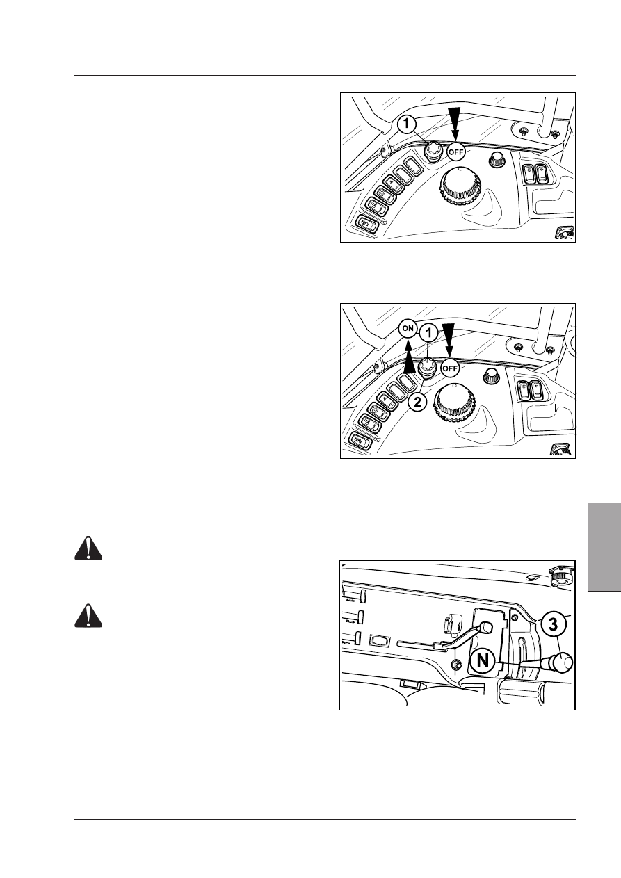
The PTO is engaged by means of the switch (1).

An indicator light on the instrument panel comes on
when the PTO is engaged.

Use: engagement/disengagement 

Engage/disengage the front PTO (1) by the ON/OFF
button switch with engine at idling speed.

Depressed button switch: disengaged PTO

Released button switch:  engaged PTO

To engage the PTO, release the switch (1) by pulling up
the locking collar (2).

Always shift the switch in the OFF disengaged position
after using the PTO or before starting the engine.

NOTE: The engine can be started only if the PTO 

engagement switch is in the OFF position and the PTO 
engagement lever (3) is in the neutral position.

Engage the PTO at a low RPM speed to protect the clutch
and driveline.

Select the operating mode and the required speed before
engaging the PTO.

IMPORTANT: For high-inertia implements (e.g. stone 
crusher, mill etc.) the universal joint for cardan shaft 
is to be used.

WARNING:  When  using  the  PTO  with  the 
tractor  at  a  standstill,  always  make  sure 
that  the  creeper  lever  of  the  gearshift  in 
neutral position and that the parking brake 
is engaged.

WARNING:  High-inertia  implements  do  not 
stop immediately after the independent PTO 
has been disengaged.  Wait for the implement 
to  slow  down  or  stop  completely  before 
performing  any  cleaning  or  adjustment 
operations.

IMPORTANT: When using implements that cause shock 

loads, always use a safety coupler between the implement 
and the PTO drive shaft. Before using the implement, check 
the correct operation both of the safety coupler and of the 
implement.

Disengagement
Fully depress the ON/OFF switch (1). The PTO indicator
light on the instrument panel goes off.

Engagement
Pull up the locking collar (2) of the ON/OFF button, then
pull the button (1) to the ON position. Now the button
will remain on the ON position, while the PTO indicator
light on the instrument panel lights up.

IMPORTANT:  When  using  implements  with  quickly 

moving  parts  (such  as  mowers,  reapers,  snowplows) 
ALWAYS  fit  an  overrun  device  on  the  implement  drive 
shaft, as a protection against possible PTO faults.

110

Operation

Power take-off operation

 [4.2.d]

PTO mode selector lever (1).

The symbols on the decal beside the c ontrol lever have
the following meanings:

A - Independent PTO engaged.

Directly driven by the engine.

CAUTION:The selector lever should always be kept 
in A position. Shift it to B only when the synchroni-
zed PTO has to be used. After the use of the syn-
chronized PTO shift the laver to A again.

B - Engagement of the ground speed synchronized

PTO (optional)

Driven by the gearbox.

NOTE: The PTO mode selector lever (1) has no neutral 

position. This is obtained when the speed selector lever 
(2) is shifted to the position “N”.

IMPORTANT:The PTO mode selector lever, independent 

or synchronized (optional), controls a mechanical coupler 
that ensures the maximum safety in both operation modes. 
The  passage  from  a  mode  to  another,  however,  is  only 
possible  when  the  teeth  are  aligned.  The  procedure  is 
described under the headings “Direct power take-off” and 
“Synchronyzed power take-off” hereunder.

Power take-off engagement

- Select the required speed 540/540ECO/1000 RPM

with the selector lever (2).

- Engage the PTO mode selector lever (1).

- Engage the power take-off (3).

- During the work, the PTO can be engaged/disenga-

ged by means of the relative control lever (3).

Direct power take-off

The direct PTO can operate at 540 RPM with the engine at
1944 RPM, or at 1000 RPM with the engine at 1956 RPM.
(At request 540ECO RPM with the engine at 1375 RPM).
The PTO is directly driven by the engine and its operation
is fully independent from the tractor’s ground speed.

Engagement of direct PTO

The direct PTO must be engaged with the engine at
idling speed, without hesitating and not caring for any
noises which are due to the alignment of the gear
teeth.
Always keep the lever on the “A” position - direct PTO
engaged.
The synchronized PTO should be engaged only when
needed (see Synchronized Power Take-Off).

X60.50 Dual Power

The  Dual  Power  system  increases  the  available  power
when working under load with engaged PTO. Dual Power
takes advantage of the potential of the electronic engine
control system to maintain steady power delivery even
when there are load variations. This is done by automa-
tically supplying an extra power reserve whilst the PTO
is  being  operated,  thus  allowing  this  latter  to  be  used
in a better way while improving the performances and
productivity.
For power values, see the Technical Specifications chapter
in this manual.

Dual Power also engages to improve performances during
transport operation according to load, ground speed and
engine speed rate.

111

Operation

5

Synchronized Power Take-Off

(Optional)

Use  of  the  synchronized  rear  power  take-off  with  the
gearbox is solely designed for towing self-driven trailers
and,  more  generally,  for  all  those  farming  implements
which have to operate synchronised with tractor move-
ment and which do not require more than 40 - 45% of
rated engine power.
Engage the synchronized power take-off with the tractor
at standstill. Depress the clutch pedal to disengage the
gearshift clutch and shift the lever (1) to the “B” position.

Synchronized PTO engagement

The synchronized PTO has to be engaged without applying
any force, with the engine at idling speed. Move the tractor
a little forward to make the engagement easier. Sometime
you may need to engage the hydraulic PTO clutch for an
instant in order to allow the gear teeth to align and make
their engagement easier. When the synchronized PTO is
not used, the lever should be shifted to the direct PTO
position (lever 1, position A).

CAUTION: When using the synchronized PTO and if 
you are forced to reverse once or several times, re-
member that the driveline inverts its spinning direc-
tion. Thus, with certain implements, it is advisable to 
disengage the PTO when reversing in order to avoid 
major damage (lever 2, position N).

Synchronized PTO revolutions (optional)

Whichever forward gear is engaged, the splined shaft
of the PTO accomplishes, for each turn of the rear
wheels:

External buttons for PTO 

engagement

Use the buttons on the rear fender (3) for easier

connection.

WARNING: Danger of entanglement. Keep well 
away  from  spinning  shafts.  Take  care  NOT 
to  remain  caught  up  by  the  PTO  driveline. 
Keep  all  the  guards  mounted  at  any  time 
on  the  transmission  shafts  of  the  tractor  or 
implements.

WARNING:  High-inertia  implements  do  not 
become  stationary  immediately  when  PTO 
is  disengaged.  Allow  sufficient  time  for 
implement  to  «run  down»  to  a  halt  before 
cleaning or adjusting.

External buttons are always active.
If the yellow switch in the cab is OFF:
- red button OFF: the PTO shaft rotation is stopped.
- yellow button ON: the PTO shaft turns slowly for 5
seconds, then stops. The switch in the cab must be
shifted to ON to start the PTO from the external but-
tons.
If the yellow switch in the cab is ON:
- red button OFF: the PTO shaft rotation is stopped.
- yellow button ON:
1 - if the button is pressed less than 5-6 seconds, the
PTO shaft turns slowly, but stops as soon as the button
is released. This function is handy when an implement
must be hitched.
2 - if the button is pressed more than 5-6 seconds, the
PTO shaft turns slowly for about 5 seconds, then starts
spinning at the set spinning rate.

WARNING: External controls must be operated 
at a safe distance, standing on one side out-
side the tractor and out of the overall width of 
mudguards. It is expressly forbidden to ope-
rate the controls from the rear of the tractor 
or standing on the inner side of wheels.

 [4.2.b]

NOTE: For a table of the revolutions of the synchronized 
power take-off output shaft for each revolution of the 
rear wheels, see the "Technical specifications" Section.

112

Operation

Speed range selection

The speed range selector lever (1) allows to change

from 540 RPM PTO (or 540ECO RPM) and back

Two speed PTO
- PTO at 540 RPM
- PTO in neutral
- PTO at 1000 RPM or 540ECO RPM

Three speed PTO
- PTO at 540 RPM
- PTO in neutral
- PTO at 1000 RPM
- PTO at 540ECO RPM

CAUTION: When the PTO is not used, the speed 
range selector lever should always be in neutral 
position.

CAUTION: Disengage the PTO clutch before switching 
between two speed ranges.

WARNING: Only use PTO at 540 RPM (or 540ECO) or 
at 1000 RPM to drive implements designed for such 
respective rotation speeds. Never allow the PTO shaft 
to rotate at more than 630 RPM with implements de-
signed for 540 RPM.

Economy PTO

A PTO speed of 540 RPM can be obtained for imple-
ments that do not require maximum power, such as
fertilizer spreaders, sprayers, etc.) by using the PTO at
540ECO RPM and decelerating to 1375 RPM. The PTO
economy mode has a number of advantages, including
a reduction in fuel consumption, noise and vibrations.

CAUTION: Economy PTO 540 ECO runs at 1375 RPM. 
Never exceed 1890 RPM engine rate (corresponding 
to 630 RPM of the PTO driveline) to avoid damages 
to the driveline itself and the connected implement.

Two speed PTO

Three speed PTO

NOTE: For the indicator of the PTO output shaft and fur-
ther indicators, see the "Instruments and programming" 
Section, Power Take-Off paragraph in this manual.

PTO overspeed
(NAO markets only)

The indicator light on the dashboard blinks if the max.
allowed rated PTO speed is exceeded.
Reduce the engine rated speed to reduce the PTO speed.
For further details, see the "Instruments and programming"
Section, Power Take-Off paragraph in this manual.


Content   ..  25  26  27  28   ..