Tractors X60 Series. Manual - part 12
 

  Index      Tractors     Tractors X60 Series - service repair manual 2012 year


Search            


Content   ..  10  11  12  13   ..


Tractors X60 Series. Manual - part 12


49

Controls - Cab

3

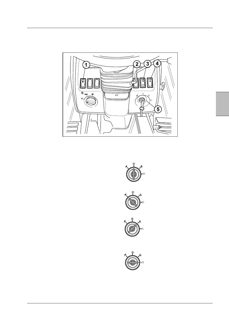
1. THERMOSTART (COLD START) SWITCH (if equipped)
(Only  equipped  on  engines  with  mechanical  injection
system)

2. SWITCH FOR UPPER HEAD LIGHTS (if equipped with
front hitch) - With the front lamp switch in third position,
press the front of the switch down: upper head lamps will
turn on and main head lamps will go off.

3. ROTATING BEACON SWITCH (if equipped)

4. HAZARD WARNING SIGNAL SWITCH

Off Position - Turn from On/Contact position
anticlockwise to stop the tractor. The key
can only be removed from this position.

Accessory  Position  -  The  radio  can  be
operated in this position and some of the
cluster displays; this position is also used
for  programming  the  digital  instrument
cluster.

On/Contact Position - All bar graphs, digital
displays, warning and indicator lamps will
be  turned  on  for  approximately  3.5  sec-
onds. This position is also used for dynamic
calibration of rear tyre size and true ground
speed sensor, if equipped.

Start Position - Turning the key fully clock-
wise against spring pressure will energise
the starter motor in addition to the circuits
already mentioned above.

CONTROLS

Controls on the dashboard

NOTE: Switch positions may vary according to tractor 
model.

5.  KEY  SWITCH  -  The  key  switch  has  four  positions  as
follows:

50

Controls - Cab

6. HEAD LAMP SWITCH -

Three Position Switch

A. First Position - All lamps OFF.

B. Second Position - Front position lamps, tail lamps, li-
cense plate lamps and the side console illumination lamp
will illuminate. Also analog cluster illumination lamps will
be ON.

C. Third Position - Front side lamps, tail lamps, license
plate lamps, the side console illumination lamp and main
head lamps will illuminate.

Four Position Switch

A. First Position - All lamps OFF.

B.  Second  position  -  ALL  amber  coloured  light  blink.
(Road - Daytime).

C.  Third  position  -  ALL  amber  coloured  light  blink.  Tail
lights and front lights light up. (Road - night).

D.  Fourth  position  -  The  light  on  the  side  console  and
the main headlights light up. The work lights switch is
activated (on field).

Direction Turn Signal, Hi/Low Beam 
Switch and Horn.

TURN SIGNALS:

Position 1 = right-hand indicator operated.

Position 2 = left-hand indicator operated.

NOTE: Self cancelling switch only: The turn signal lamps 
will continue to flash until the steering wheel is turned in 
the opposite direction. You can override this function to 
cancel the indicator by moving the switch in the oppo-
site direction chosen.

HEADLAMP HI/LOW BEAM:

Position 3 = With the headlamp hi/low beam switch in the
third or fourth position, push the lever toward the steering
wheel then release it. The hi beam in the headlights will
be selected (blue indicator light on the instrument panel
will go on). Lifting the switch again will select low beam
(blue indicator lamp will go off).
With headlamp switch in First or Second position, lifting
the switch towards the steering wheel and releasing will
flash the headlamps.

HORN:

Press the end of the switch to operate.

51

Controls - Cab

3

-  Comply  with  road  traffic  laws,  including  any  speed

restrictions and the correct use of Hazard

 Warning Lamps and SMV Symbol.
-  Connect  the  brake  pedals  together  with  the  brake

pedal interlock. This will ensure uniform braking and
maximum stopping ability.

-  Check  clearance  before  going  under  electric  power

lines, bridges etc.

Tractor Warning Lamp Usage
North American Tractors

-  The flashing amber warning lamps must be used ac-

cording to road traffic laws.

The flashing amber warning lamps must be used when
operating the tractor on the road during the day or night.
A vehicle operator that comes near the tractor must see
an SMV symbol and the tail lamps from the rear and the
flashing amber warning lamps from the front and rear.

1. AMBER WARNING LAMP AND TURN SIGNAL LAMP

(LEFT SIDE)

2. AMBER WARNING LAMP AND TURN SIGNAL LAMP

(RIGHT SIDE)

3. TAIL LAMP (RIGHT SIDE)
4. TAIL LAMP (LEFT SIDE)
5. SLOW MOVING VEHICLE (SMV) SYMBOL


  Highway/Public Road Operation

Use of amber hazard warning lights

Amber hazard warning are operated by turning the main
light switch clockwise to the 1st and 2nd position.

FIRST POSITION (1) - ALL amber hazard lights are blink-
ing.

SECOND POSITION (2) - ALL hazard warning lights are
blinking, and front and rear side lights light up.

When the direction turn signal switch is used, the amber
warning lamps will operate as follows:

1. When indicating to turn right, the Right amber warning

lamp will flash ON and OFF and the Left amber warning
lamp will illuminate but will not flash.

2. On the contrary, when indicating to turn left, the Left

amber light blinks and the right one lights up, but does
not blink.

IMPORTANT:  When  towing  an  implement  or  wagon 
with the tractor, the complete rear area warning system 
(amber warning lamps, red tail lamps and SMV symbol) 
must be easily seen by any vehicle operator coming near 
the tractor.

52

Controls - Cab

Rotating Beacon
(if equipped).

-  The rotating amber beacon must be used according to

local road traffic laws.

The rotating amber beacon is operated by pressing the
switch (2) with the flashing beacon symbol.

Slow Moving Vehicle (SMV) Symbol
(if equipped).

-  For correct use of the SMV symbol (3), observe local

road traffic laws.

If a Slow Moving Vehicle (SMV) symbol is equipped it must
be installed on the rear part of the tractor.

To install the SMV symbol on an implement or trailer a
special bracket must be obtained from your dealer.

1

WARNING: Collision of high speed road traf-
fic  and  tractors  or  implements  can  cause 
personal  injury  or  death.  On  roads,  use 
amber  warning  lamps  according  to  local 
laws. Keep SMV emblem visible. Pull over to 
let faster traffic pass. Slow down and signal 
before turning off.

Tractor Warning Lamp Usage - Rest 

Of World Tractors

-
 The flashing amber warning lamps must be used ac-

cording to road traffic laws.

The amber warning lamps are used to indicate a hazard
to other road users. To operate, press the switch (1) as
shown above. ALL the amber warning lamps will flash
ON and OFF.

IMPORTANT:  When  operating  the  tractor,  towing  an 
implement  or  trailer,  the  complete  rear  area  warning 
system (amber warning lamps, when applicable, and red 
tail lamps) must be easily seen by any vehicle operator 
coming near the tractor.

Implement warning lamps
(if equipped).

It  is  recommended  that  implement  warning  lamps  are
used:

-  If the flashing warning lamps and red tail lamps on the

tractor cannot be seen because they are obstructed by
the implement.

-  If the towed implement is 1219 mm or more behind the

hitch point of the tractor.

-  If the towed implement is 1219 mm or more to the left

or right of the centre of the tractor.

-  If  the  towed  implement  has  a  minimum  3000  mm

width.

Install the warning lamps to indicate the side of the imple-
ment nearest the centre of the road.


Content   ..  10  11  12  13   ..