Snowmobile Arctic Cat (2000 year). Manual - part 161
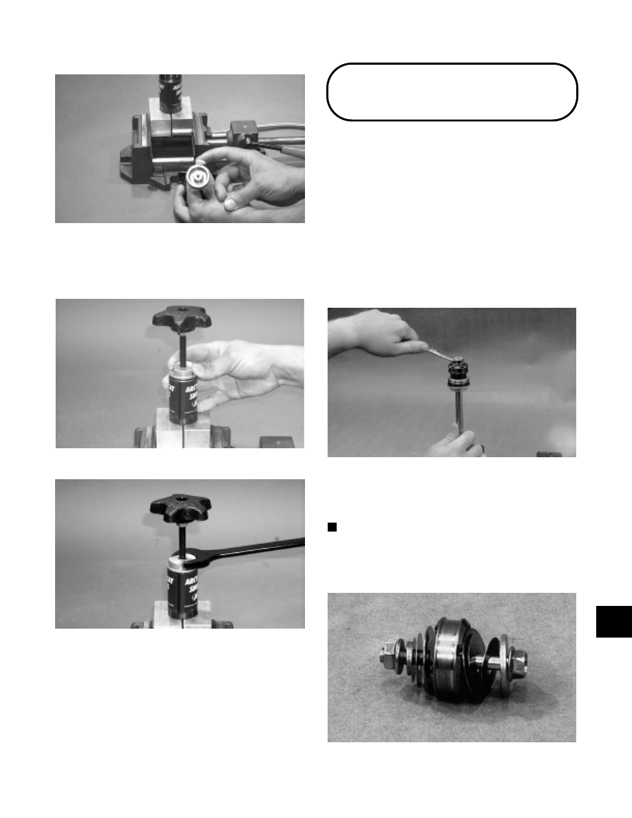
Fig. 9-514
AG828
10. Install the adjuster knob making sure the knob is
turned out (counterclockwise) completely. Tighten
securely.
Fig. 9-515
AG829
Fig. 9-516
AG830
11. There must be a 1/4 to 1 turn of free-play on the
k n o b. I f h a n d l e f r e e - p l a y i s n o t w i t h i n
specifications, repeat steps 1-10.
Installing Internal
Travel Limiting Spacers
These spacers are used to shorten the travel of the shock
absorber to fine tune the suspension to the operator’s
driving style.
If installing the spacers in the internal floating piston
shock absorbers used on the 1992-2000 models, follow
these steps.
1. Disassemble the shock absorber as covered in this
manual.
2. Place the shock shaft eyelet into a vise and remove
the nut securing the piston to the shock shaft.
Fig. 9-517
AP028
3. Carefully remove the piston and its valving plates
stacked on either side of the piston from the end of
the shock shaft.
NOTE: When removing the piston and valve plates
from the shock shaft, place the piston assembly on
a 5/16 x 3-in. cap screw and secure with a nut to
keep the assembly in its proper order.
Fig. 9-518
AP032
9
9-167