Snowmobile Arctic Cat (2000 year). Manual - part 144
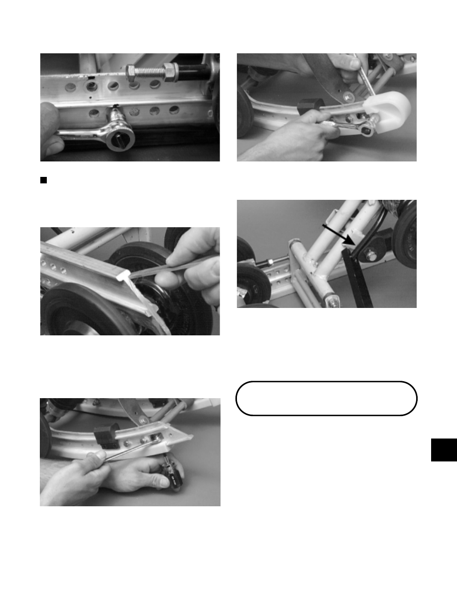
Fig. 9-371
AG694D
NOTE: Apply a light coat of grease to the slide rail
surface to aid in installing a new wear strip. If there
are any sharp edges on the lower portion of the rail,
use a file to remove them.
Fig. 9-372
AG534D
13. From the back, start the wear strip onto the rail; then
using a block of wood and a hammer, drive the wear
strip forward into position. Secure with a machine
screw and lock nut. Tighten to 1.1 kg-m (8 ft-lb).
Fig. 9-373
AG509D
14. Secure the end cap onto the slide rail using a cap
screw, flat washers, and a lock nut. Tighten to 1.1
kg-m (8 ft-lb).
Fig. 9-374
AG506D
15. Install the short spring leg onto the adjusting cam.
Fig. 9-375
AG516DA
16. Adjust suspension.
17. After the skid frame has been installed, adjust track
tension deflection (see Track Tension in this
sub-section) and track alignment (see Track
Alignment in this sub-section).
Installing Skid Frame
1. Place a piece of cardboard on the floor to protect
against scratching and tip the snowmobile onto one
side.
2. Pull the track away from the tunnel and spread
open; then place the skid frame into the track.
3. Position the front of the skid frame into the tunnel
and align the front arm with the appropriate
mounting hole in the tunnel. Insert the cap screw
with washers through the tunnel mounting hole and
through the front arm. DO NOT TIGHTEN AT
THIS TIME. Repeat this procedure on the other
side.
9
9-99