Snowmobile Arctic Cat (2000 year). Manual - part 139
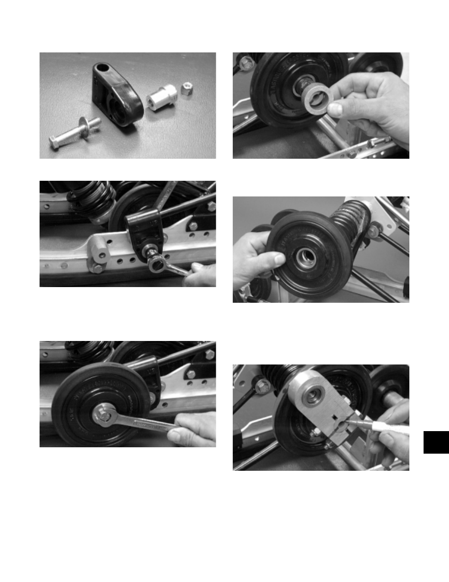
Fig. 9-265
AG680D
Fig. 9-266
AG679D
3. Install the front outer idler wheel; then secure with
the cap screw, washer, and lock nut. Tighten to
3.2 kg-m (23 ft-lb).
Fig. 9-267
AG678D
4. Install the spacer.
Fig. 9-268
AG677D
5. Install the rear upper idler wheel on the idler arm.
Fig. 9-269
AG545D
6. Making sure the marks made during disassembly
are aligned, install the offset pivot idler to the idler
arm and secure with the cap screws, washers, and
lock nuts. Tighten to 2.6 kg-m (19 ft-lb).
Fig. 9-270
AG675D
7. Place the short spring leg onto the adjusting cam
using the rear suspension spring tool.
9
9-79