Snowmobile Arctic Cat (2000 year). Manual - part 137


  Index      Snowmobiles / ATV     Snowmobile Arctic Cat - service manual 2000 year


Search            


Content   ..  135  136  137  138   ..


Snowmobile Arctic Cat (2000 year). Manual - part 137


INSTALLING

NOTE: Apply a light coat of grease to the slide rail

surface to aid in installing a new wear strip. If there
are any sharp edges on the lower portion of the rail,
use a file to remove them.

Fig. 9-227

AG534D

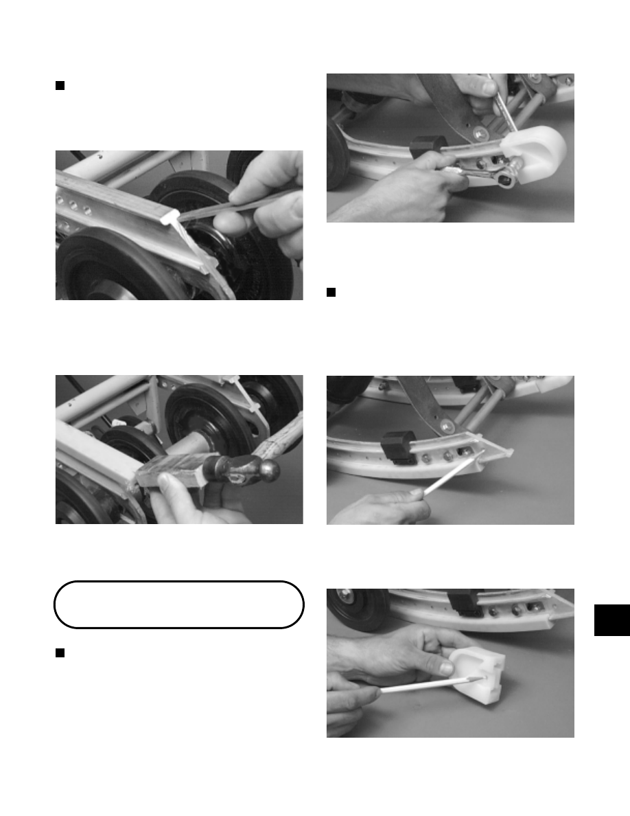
1. From the back, start the wear strip onto the rail; then

using a block of wood and a hammer, drive the wear
strip forward into position.

Fig. 9-228

AG535D

2. Secure with a machine screw and lock nut. Tighten

to 1.1 kg-m (8 ft-lb).

End Caps

NOTE: The skid frame does not have to be

removed for this procedure.

REMOVING

1. Remove the lock nut, washers,  and cap screw

securing the end cap.

Fig. 9-229

AG506D

2. Using a hammer, tap the end cap off the rail.

CLEANING AND INSPECTING

NOTE: Whenever a part is worn excessively,

cracked, or damaged in any way, replacement is
necessary.

1. Inspect the end cap area of the slide rail for cracks

and wear.

Fig. 9-230

AG507D

2. Inspect the end cap for any signs of cracking or

wear.

Fig. 9-231

AG508D

3. Clean both the slide rail area and the end cap. Using

compressed air, clean the areas of dirt and gravel.

9

9-71

! WARNING

Always wear an approved pair of safety glasses
when using compressed air.

4. Inspect the cap screw for cracked, stretched, or

damaged threads. Use a new lock nut when
assembling.

INSTALLING

1. Position the end cap on the slide rail; then align the

hole in the end cap with the hole in the slide rail.

2. Secure with a cap screw, washers, and lock nut.

Tighten to 1.1 kg-m (8 ft-lb).

Shock Pads

NOTE: The skid frame does not have to be

removed for this procedure.

REMOVING

1. Using a 3/16-in. drill bit drill out the rivets securing

the shock pad to the slide rail. Account for the
retaining brackets.

Fig. 9-232

AG476D

2. Remove the shock pad.

INSPECTING

NOTE: Whenever a part is worn excessively,

cracked, or damaged in any way, replacement is
necessary.

1. Inspect the pad and retaining brackets for damage

or wear.

2. Inspect the rivet holes in the slide rail for damage or

elongation.

INSTALLING

1. Place the pad and retaining brackets into position

on the slide rail.

2. Secure the pad assembly with rivets.

Fig. 9-233

AG531D

Front Outer

Idler Wheels

NOTE: The skid frame does not have to be

removed for this procedure.

REMOVING

1. Remove the cap screws and lock nuts securing the

front outer idler wheel and the idler wheel mounting
block. Account for flat washers and an axle.

Fig. 9-234

AG678D

9-72

Fig. 9-235

AG686D

2. Note the locations of the flat washers for assembly

purposes. The washers are to be installed next to the
idler wheels.

Fig. 9-236

AG622D

CLEANING AND INSPECTING

NOTE: Whenever a part is worn excessively,

cracked, or damaged in any way, replacement is
necessary.

1. Clean the bearing with a clean cloth.

2. Inspect each idler wheel and each plastic hub for

cracks or damage.

3. Rotate the idler wheel bearing (by hand) and

inspect for binding or roughness.

4. If a bearing must be replaced, use this procedure.

Do not remove the bearing unless it is absolutely
necessary. The bearing will be damaged during
removal.

A. Remove the wheel insert and the snap ring.

B. Using a hydraulic press, press the bearing out from

the inside of the wheel.

C. Press the new bearing (on its outer race) into the

idler wheel.

Fig. 9-237

AG538D

D. Install the snap ring making sure the “sharp side”

is directed away from the bearing.

Fig. 9-238

AG539D

E. Install the insert.

Fig. 9-239

AG540D

INSTALLING

1. Secure the mounting block on the slide rail with a

cap screw and lock nut. Tighten to 3.2 kg-m (23
ft-lb).

! CAUTION

9

9-73

Fig. 9-240

AG686D

2. Place the idler wheel and axle against the mounting

block making sure there is a flat washer on both
sides of the idler wheel.

Fig. 9-241

AG622D

Fig. 9-242

AG623D

3. Secure the idler wheel assembly with a cap screw

and a lock nut. Tighten cap screws to 3.2 kg-m (23
ft-lb).

Fig. 9-243

AG618D

Rear Inner

Idler Wheels

NOTE: The skid frame does not have to be

removed for this procedure.

REMOVING

1. Remove the cap screws and lock washers securing

the rear inner idler  wheel and  the idler  wheel
mounting block. Account for a flat washer and an
axle.

Fig. 9-244

AG672D

9-74


Content   ..  135  136  137  138   ..