Snowmobile Arctic Cat (2000 year). Manual - part 132
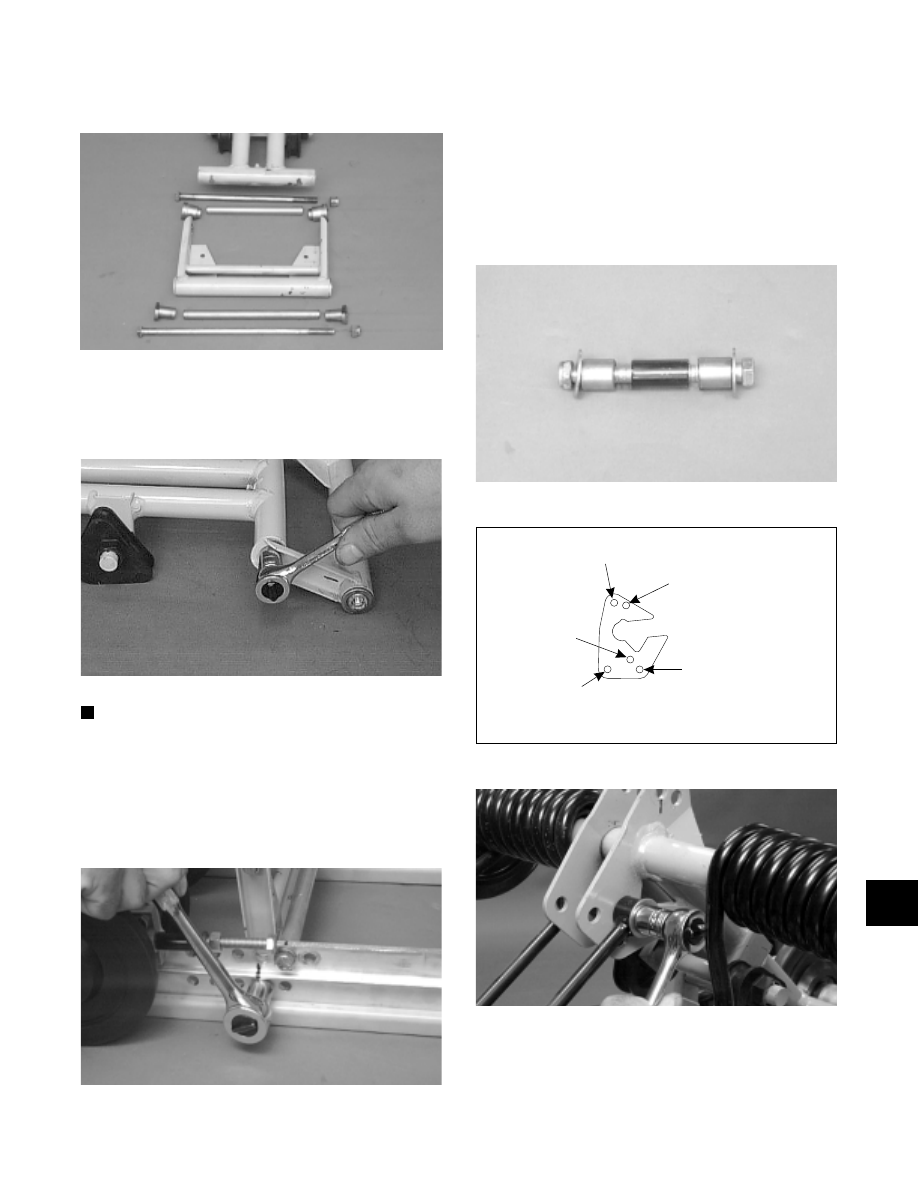
ASSEMBLING
Fig. 9-130
AG562D
1. Install the rear arm onto the idler arm with an
aluminum axle, bushing assemblies, cap screw, and
a lock nut. Tighten to 3.2 kg-m (23 ft-lb).
Fig. 9-131
AG477D
NOTE: Install the rear arm assembly into the
appropriate mounting hole as noted during
disassembly.
2. Place the rear arm assembly into position (with the
brace facing towards the front side) between the
slide rails. Secure with a cap screw and lock nut.
Tighten to 3.2 kg-m (23 ft-lb).
Fig. 9-132
AG558D
3. Position the shock links in the appropriate holes of
the idler arm brackets (see 2000 Suspension
Mounting Location Chart in this section). Place a
spacer between the center of the brackets; then
place a flat washer on the cap screw. Insert the axle
links into the upper shock link eyelets; then insert
the cap screw with washer through the eyelets.
Secure with a cap screw, washer, and lock nut.
Tighten to 3.2 kg-m (23 ft-lb).
Fig. 9-133
AG556D
Fig. 9-134
732-688F
Fig. 9-135
AG682D
4. Place the upper shock eyelet with bushings between
the idler arm brackets making sure the spacer is
properly positioned between the brackets. Secure
with a cap screw and lock nut. Tighten to 3.2 kg-m
(23 ft-lb).
B
Rear Shock Link
Mounting Holes A & B
Rear Shock
Mounting Hole
Do Not Use
A
Do Not Use
9
9-51