Snowmobile Arctic Cat (2000 year). Manual - part 129
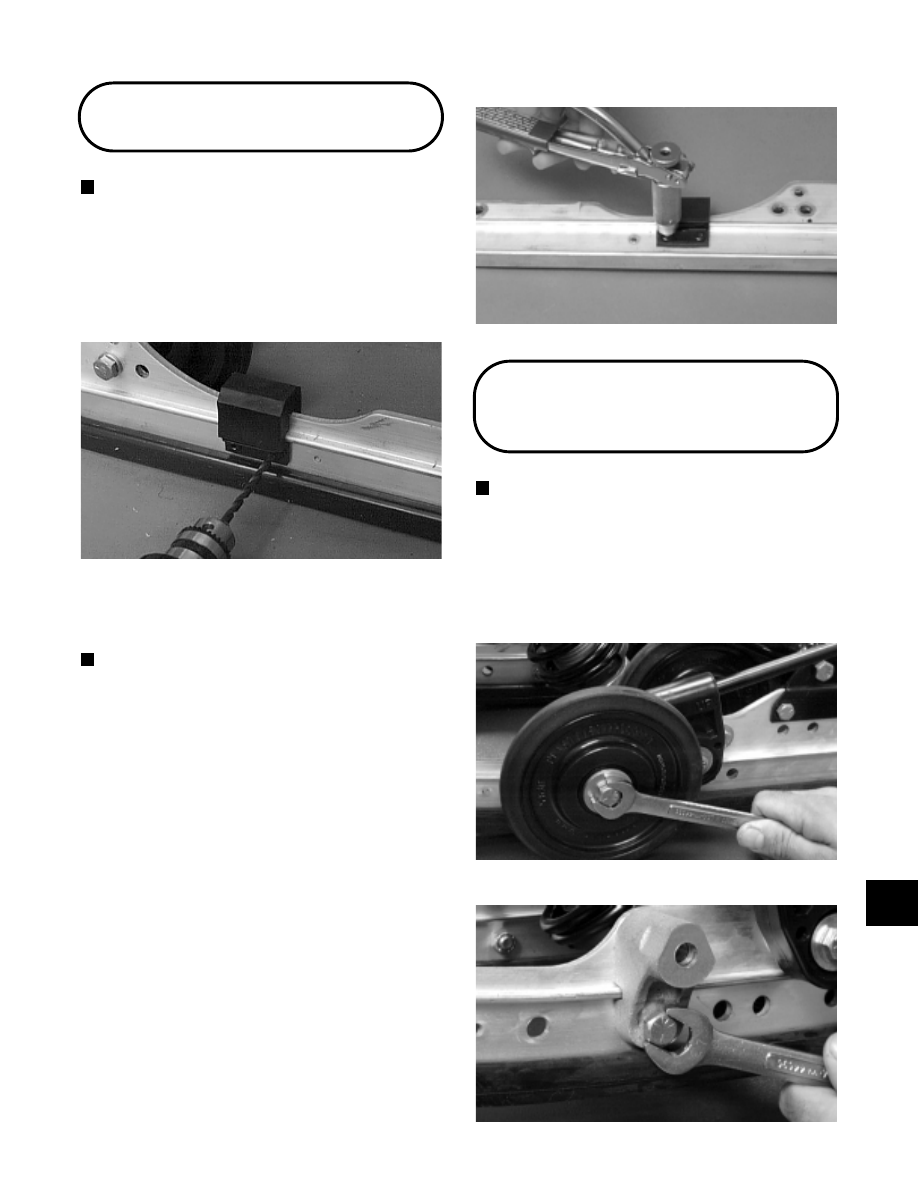
Shock Pads
NOTE: The skid frame does not have to be
removed for this procedure.
REMOVING
1. Using a 3/16-in. drill bit drill out the rivets securing
the shock pad to the slide rail. Account for the
retaining brackets.
Fig. 9-71
AG476D
2. Remove the shock pad.
INSPECTING
NOTE: Whenever a part is worn excessively,
cracked, or damaged in any way, replacement is
necessary.
1. Inspect the pad and retaining brackets for damage
or wear.
2. Inspect the rivet holes in the slide rail for damage or
elongation.
INSTALLING
1. Place the pad and retaining brackets into position
on the slide rail.
2. Secure the pad assembly with rivets.
Fig. 9-72
AG531D
Front Outer
Idler Wheels
NOTE: The skid frame does not have to be
removed for this procedure.
REMOVING
1. Remove the cap screws and lock nuts securing the
front outer idler wheel and the idler wheel mounting
block. Account for flat washers and an axle.
Fig. 9-73
AG678D
Fig. 9-74
AG686D
9
9-39