Snowmobile Arctic Cat (2000 year). Manual - part 101
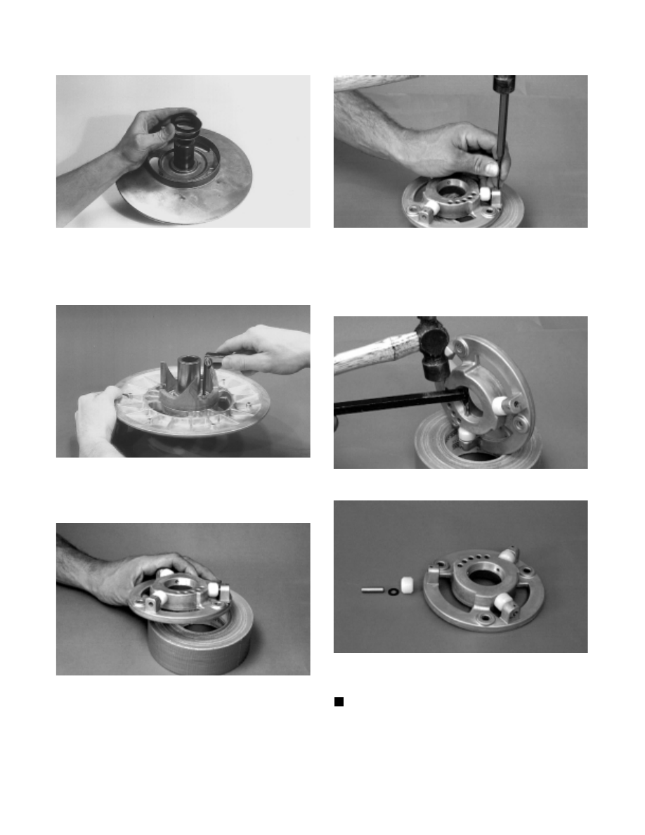
Fig. 8-36
B460
6. Remove the three socket-head cap screws and lock
washers securing the torque bracket (cam) to the
stationary sheave; then remove torque bracket.
Fig. 8-37
AI062
7. Place the roller plate on a work fixture (roll of duct
tape, etc.).
Fig. 8-38
SC004D
8. Using a 1/8-in. punch, remove the roll pin securing
the roller, pin, and thrust washer to the plate.
Fig. 8-39
SC005D
9. Using the Roller Pin Removal Tool (p/n 0644-276)
from inside the plate, drive the roller pin out of the
plate. Account for the pin, thrust washers, and
roller.
Fig. 8-40
SC006D
Fig. 8-41
SC007D
CLEANING AND INSPECTING
NOTE: Whenever a part is worn excessively,
cracked, or damaged in any way, replacement is
necessary.
1. Using parts-cleaning solvent, wash grease, drive
belt dust, and foreign matter off all components.
8-10