Snowmobile Arctic Cat (2000 year). Manual - part 100


  Index      Snowmobiles / ATV     Snowmobile Arctic Cat - service manual 2000 year


Search            


Content   ..  98  99  100  101   ..


Snowmobile Arctic Cat (2000 year). Manual - part 100


12. Inspect the stationary sheave and shaft for damage

or wear.

ASSEMBLING

Fig. 8-17

0734-069

! WARNING

Never reuse the lock nuts on the cam arm pins.

1. Place a cam arm with bushing and washers into

position on the movable sheave; then secure with
the cam arm pin and lock nut. Carefully tighten the
lock nut until it contacts the cam arm pin shoulder;
then tighten an additional 1/8 turn. Repeat
procedure on the other two cam arms making sure
the head of each pin is positioned  toward the
direction of drive clutch rotation.

NOTE: The drive clutch rotates counterclockwise.

Fig. 8-18

733-452B

2. Place a roller and washers (one on each side of the

roller) into position on the spider; then install the
pin. Repeat procedure on the other two rollers.
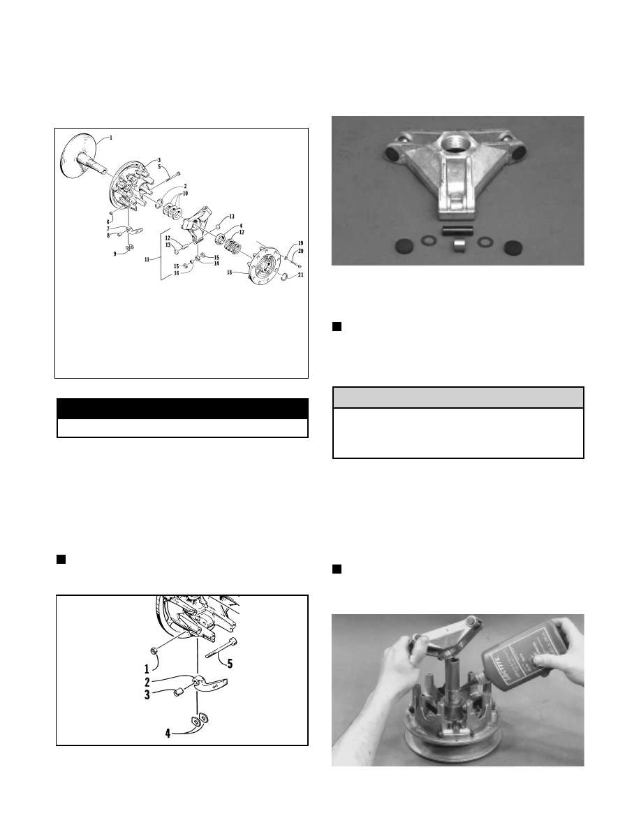
Fig. 8-19

AM071D

3. Place the spider buttons into position; then tap into

place until firmly seated.

NOTE: If a spider button does not fit tightly, it must

be replaced.

4. Align the spider and movable sheave timing marks.

Failure to align the spider and movable sheave
timing marks will cause drive clutch to be out of
balance resulting in clutch and crankshaft
damage.

5. Place the movable sheave, spacer rings, and spider

into position on the stationary sheave hub. Make
sure all threads are clean and free of oily residue.
Apply green Loctite #620 to the entire threaded
area of the shaft and thread the spider onto the shaft.
Tighten the spider using the spider removal tool to
34.5 kg-m (250 ft-lb).

NOTE: Allow the Loctite to cure at room

temperature for 24 hours.

Fig. 8-20

AM072A

KEY

1. Sheave
2. Snap Ring
3. Sheave
4. Nut
5. Pin
6. Lock Nut
7. Cam Arm
8. Bushing
9. Washer

10. Spacer Washer
11. Spider Assy
12. Spider Pin

13. Spider Button
14. Roller
15. Washer
16. Bearing
17. Spring
18. Cover
19. Lock Washer
20. Cap Screw
21. Snap Ring

! CAUTION

8-6

6. Apply green Loctite #620 to the threads of the

stationary shaft above the spider. Install the large
jam nut and tighten to 11.8 kg-m (85 ft-lb).

Fig. 8-21

AM066

NOTE: Grasp the movable sheave and lift it

upward; then release it. It must move freely and not
bind at any point.

7. Place the spring and cover into position making

sure the timing mark on the cover is properly
aligned; then compress the spring and install the
nine cap screws coated with blue Loctite #242 and
lock washers. Tighten evenly to 1.4 kg-m (10 ft-lb).

Fig. 8-22

AM075

Fig. 8-23

AM076

Care must be taken when installing the cover not
to damage the bushing.

INSTALLING

1. Install any spacers as accounted for in removing;

then insert the clutch bolt with lock washer.

NOTE: Be sure to wipe the clutch taper and

crankshaft taper clean of any oil film or dirt before
installing the drive clutch.

2. Place the clutch into position on the crankshaft.

3. Using a 12-point 1/2-in. socket and the drive clutch

spanner wrench, tighten the clutch bolt to 6.9-7.6
kg-m (50-55 ft-lb).

When installing the drive clutch, do not tighten
the  clutch  bolt with any  kind of  impact  tool.
Tighten clutch bolt using a hand torque wrench
only. Failure to do so could result in stationary
sheave damage.

Fig. 8-24

AF477D

4. Check alignment between the drive clutch and driven

pulley (see Drive Clutch/Driven Pulley in this section).

Fig. 8-25

AF468D

! CAUTION

! CAUTION

8

8-7

5. Install the drive belt. Check drive belt deflection

(see Drive Clutch/Driven Pulley in this section).
Secure the belt guard and install the plug in the
belly pan.

! WARNING

Never operate the engine without the belt guard
secured.

6. Either test drive the snowmobile or run the engine

for five minutes; then tighten the drive clutch bolt to
6.9-7.6 kg-m (50-55 ft-lb).

REPLACING CAM ARM BUSHINGS

1. Using a vise, spread the jaws just enough to allow

room for the bushing to pass between.

2. Position the cam arm over the spread jaws.

Fig. 8-26

AM094

3. Slide a new bushing onto one of the cam arm pins;

then position the pin through the cam arm bushing.

Fig. 8-27

AM095

4. Using the new bushing as a tool, drive the worn

bushing from the cam arm. When the head of the
cam arm pin contacts the cam arm, the new bushing
will be properly seated.

Fig. 8-28

AM096

Driven Pulley

REMOVING

1. Open the hood; then open the belt guard.

2. Remove the drive belt.

3. Remove the cap screw and washer securing the

driven pulley; then account for and note the position
of any alignment washers.

Fig. 8-29

SC013D

4. Slide the driven pulley off the driven shaft; then

remove pulley from the engine compartment.

NOTE: If the driven pulley is tight on the shaft, pull

the driven pulley off using the Driven Pulley Puller
(p/n 0744-023).

5. Remove the key, alignment washers, and stub shaft

from the driven shaft.

8-8

Fig. 8-30

AF120D

DISASSEMBLING

1. Scribe a line across all driven pulley components to

ensure correct assembly and pulley balance.

Fig. 8-31

SC001D

2. Place the driven pulley on a work fixture so the

roller plate is directed upward.

Fig. 8-32

SC002D

NOTE: To aid in driven pulley servicing, use a roll

of duct tape as a work fixture. The work fixture will
increase the stability of the pulley during the repair
procedure.

3. Remove the three lock nuts securing the roller plate;

then carefully slide the plate off the stationary shaft
allowing the spring to release tension.

! WARNING

The roller plate is under spring pressure. Care
must be taken when removing the lock nuts to
prevent the plate from ejecting prematurely.

Fig. 8-33

SC003D

4. Remove the spring.

Fig. 8-34

B458D

5. Slide the movable sheave off the stationary shaft; then

remove any washers located between the sheaves
noting the position of washers for assembling
purposes.

Fig. 8-35

B459D

8

8-9


Content   ..  98  99  100  101   ..