Snowmobile Arctic Cat (2000 year). Manual - part 71
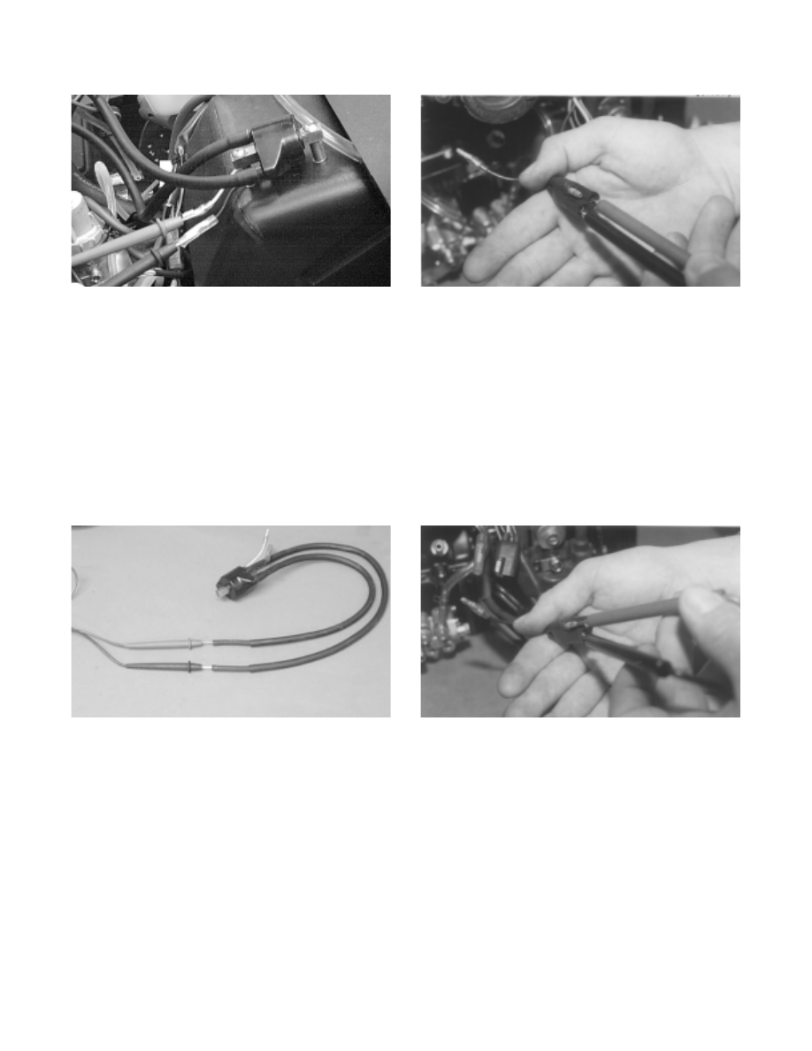
Fig. 5-33
AK051D
4. Ignition coil primary resistance must be between
0.25-0.34 ohm.
IGNITION COIL (SECONDARY)
1. Remove the spark-plug caps from the high tension
wires.
2. Set the selector in the X1K position.
3. Connect the red meter lead to one high tension wire;
then connect the black meter lead to the other high
tension wire.
Fig. 5-34
AK050D
4. Ignition coil secondary resistance must be between
6800-10,200 ohms.
CHARGE COIL (1)
1. Disconnect the triple-wire plug from the CDI unit
to the magneto.
2. Set the selector in the X100 position.
3. Connect the red meter lead to the red/white wire in
the plug; then connect the black meter lead to the
black/white wire in the plug.
Fig. 5-35
AK014
4. Charge coil (1) resistance must be between 128-192
ohms.
CHARGE COIL (2)
1. Disconnect the triple-wire plug from the CDI unit
to the magneto.
2. Set the selector in the X1 position.
3. Connect the red meter lead to the black/red wire in
the plug; then connect the black meter lead to the
red/white wire in the plug.
Fig. 5-36
AK013
4. Charge coil (2) resistance must be between
13.6-20.4 ohms.
LIGHTING COIL
1. Disconnect the main wiring harness from the
engine.
2. Set the selector in the X1 position.
3. Connect the two meter leads to each of the yellow
leads in the connector from the engine.
5-30