Snowmobile Arctic Cat (2000 year). Manual - part 69


  Index      Snowmobiles / ATV     Snowmobile Arctic Cat - service manual 2000 year


Search            


Content   ..  67  68  69  70   ..


Snowmobile Arctic Cat (2000 year). Manual - part 69


ADJUSTING TPS

NOTE: Before using the TPS adjustment  tool,

verify its battery condition. The battery used in the
tool is a 9-volt battery.

To check battery condition, use a digital volt/ohmmeter
set on DC volt scale. Test between the adjustment tool
black and red jacks. Insert the red lead of the digital
voltmeter into the green jack of the adjustment tool and
the black lead of the digital voltmeter into the black jack
of the adjustment tool. If voltage is found below 4.9
volts, replace the battery.

1. Loosen the two screws securing the TPS.

2. Using TPS Adjustment Tool (p/n 0644-299),

connect its wiring harness to the TPS. Connect the
two meter leads (red and black) using the two pin
jack adapters provided with the adjustment tool to
the red and black jacks of the TPS adjustment tool.

3. Set the selector to the DC scale. Adjust the TPS to

the specifications in the following chart with the
throttle fully closed; then tighten the two screws
securing the TPS.

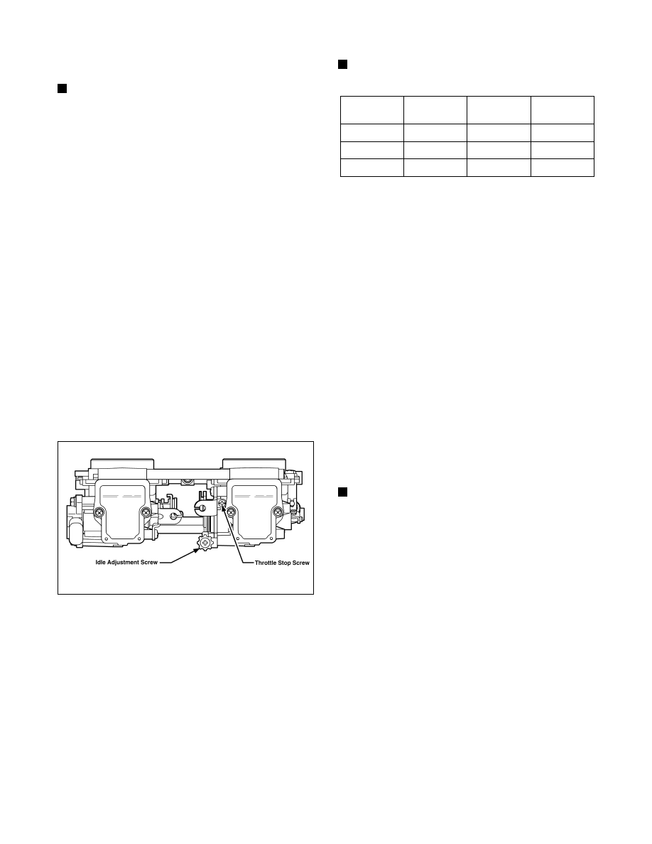
4. Squeeze the throttle to the wide-open position. If

the reading is not as specified in the following chart,
adjust the throttle stop screw  until the correct
voltage is indicated on the voltmeter.

Fig. 5-9

0734-457

5. Connect the  throttle cable to the  throttle shaft.

Adjust the throttle cable, if required, so that both the
idle and wide-open positions are obtainable while
working the throttle lever. Keep in mind that there
must be no free-play in the throttle lever in the idle
position.

6. Check the idle voltage using the TPS Adjustment

Tool (p/n 0644-299). Adjust the idle voltage to the
specifications in the following chart using the idle
adjustment screw.

7. Disconnect the adjustment tool harness from the

TPS. Connect the snowmobile TPS harness to the
newly installed or adjusted TPS.

NOTE: Before installing the TPS harness

connector, apply dielectric grease to the connector
pins.

REPLACING TPS

1. Disconnect the throttle cable from the throttle shaft.

2. Turn the idle speed screw counterclockwise until its

end no longer contacts the throttle stop. The throttle
valves should now be completely closed.

3. Disconnect the TPS wiring harness connector.

Remove the two screws securing the TPS to the
right-side carburetor.

4. Install the new TPS and secure with two screws, flat

washers, and lock washers.

FAIL-SAFE IGNITION TIMING

Engines equipped with the 3-D ignition system have a
protective  feature called  “fail-safe” ignition timing
which prevents engine damage should the TPS fail. If
the TPS does fail, the engine will run normally at low
RPM but will run poorly at high RPM. This will allow
the operator to get the snowmobile to safety with little
or no engine damage.

NOTE: The engine will continue to operate this

way until the TPS is replaced.

WIDE-OPEN POSITION

Engine

Closed

Position

Idle

Position

Wide-Open

Position

700 cc

0.025 V

0.325 V

3.920 V

800 cc

0.300 V

0.600 V

4.012 V

1000 cc

0.300 V

0.600 V

4.012 V

5-22

Testing Electrical

Resistances

(EFI Models)

NOTE: Resistance tests of the engine electrical

components should be made using the Fluke
Multimeter only. Analog-style multitesters may not
be accurate enough to use in these critical tests.
Replace any component that does not have a test
value within specifications.

IGNITION COIL (PRIMARY)

1. Disconnect the double wire plug from the ECU to

the ignition coil.

2. Set the selector in the X1 position.

3. Connect the red meter lead to the orange lead; then

connect the black meter lead to the black lead.

Fig. 5-10

AK051D

4. Ignition coil primary resistance must be between

0.25-0.34 ohm.

IGNITION COIL (SECONDARY)

1. Remove the spark-plug caps from the high tension

wires.

2. Set the selector in the X1K position.

3. Connect the red meter lead to one high tension wire;

then connect the black meter lead to the other high
tension wire.

Fig. 5-11

AK050D

4. Ignition coil secondary resistance must be between

6800-10,200 ohms.

CHARGE COIL (High Speed)

1. Disconnect the triple-wire plug from the ECU to the

magneto.

2. Set the selector in the X1 position.

3. Connect the red meter lead to the black wire

(500/580 cc) or to the green/red wire (600 cc) in the
plug; then connect the black meter lead to the green
wire (500/580 cc) or to the brown/white wire (600
cc) in the plug.

Fig. 5-12

AK014

4. Charge coil (high speed) resistance must be

between 36.8-55.2 ohms (500/580 cc) or 13.6-20.4
ohms (600 cc).

CHARGE COIL (Low Speed)

1. Disconnect the triple-wire plug from the ECU to the

magneto.

2. Set the selector in the X100 position (500/580 cc)

or X10 (600 cc).

5

5-23

3. Connect the red meter lead to the brown wire

(500/580 cc) or to the black/red wire (600 cc) in the
plug; then connect the black meter lead to the green
wire (500/580 cc) or to the green/red wire (600 cc)
in the plug.

Fig. 5-13

AK013

4. Charge coil (low speed) resistance must be between

360-540 ohms (500/580 cc) or 13.6-20.4 ohms (600
cc).

LIGHTING COIL

1. Disconnect the main wiring harness from the

engine.

2. Set the selector in the X1 position.

3. Connect the two meter leads to each of the yellow

leads in the connector from the engine.

Fig. 5-14

AK015

4. Lighting coil resistance must be between 0.07-0.10

ohm (500/580 cc) or 0.08-0.12 ohm (600 cc).

IGNITION TIMING SENSOR

1. D i s c o n n e c t t h e t wo t i m i n g s e n s o r l ea d s

(green/white and brown) from the ECU.

2. Connect the meter leads to the sensor leads.

3. Ignition timing sensor resistance must be between

152-228 ohms.

SPARK-PLUG CAP

1. Remove the spark-plug caps from the high tension

wires.

2. Set the selector in the X1K position.

3. In turn on each cap, touch a tester lead to each end

of the spark-plug cap.

Fig. 5-15

B170

4. Spark-plug cap resistance must be between

4000-6000 ohms.

IGNITION SWITCH

1. Remove the main wiring harness connectors from

the ignition switch.

2. Rotate the key to the OFF position.

3. The meter must read less than 1 ohm resistance

between the ignition switch terminals.

4. Rotate the key to the RUN position.

5. The meter must read OL (infinite resistance).

Testing Electrical

Resistances

(Fan Cooled Models)

NOTE: Resistance tests of the engine electrical

components should be made using the Fluke
Multimeter only. Analog-style multitesters may not
be accurate enough to use in these critical tests.
Replace any component that does not have a test
value within specifications.

IGNITION COIL (PRIMARY)

1. Disconnect the two connectors from the CDI unit to

the ignition coil.

2. Set the selector in the X1 position.

5-24

3. Connect the red meter lead to the orange lead; then

connect the black meter lead to the black lead.

Fig. 5-16

AK051D

4. Ignition coil primary resistance must be between

0.25-0.34 ohm.

IGNITION COIL (SECONDARY)

1. Remove the spark-plug caps from the high tension

wires.

2. Set the selector in the X1K position.

3. Connect the red meter lead to one high tension wire;

then connect the black meter lead to the other high
tension wire.

Fig. 5-17

AK050D

4. Ignition coil secondary resistance must be between

6800-10,200 ohms.

CHARGE COIL

1. Disconnect the triple-wire plug from the CDI unit

to the magneto.

2. Set the selector in the X100 position.

3. Connect the red meter lead to the red/white wire in

the plug; then connect the black meter lead to the
black/red wire in the plug.

Fig. 5-18

AK013

4. Charge coil resistance must be between 128-192

ohms.

LIGHTING COIL

1. Disconnect the main wiring harness from the

engine.

2. Set the selector in the X1 position.

3. Connect the two meter leads to each of the yellow

leads in the connector from the engine.

Fig. 5-19

AK015

4. Lighting coil resistance must be between 0.17-0.26

ohm.

SPARK-PLUG CAP

1. Remove the spark-plug caps from the high tension

wires.

2. Set the selector in the X1K position.

3. In turn on each cap, touch a tester lead to each end

of the spark-plug cap.

5

5-25


Content   ..  67  68  69  70   ..