Snowmobile Arctic Cat (2000 year). Manual - part 68
4. If an adjustment is necessary, loosen the switch
bracket screws, move the switch up, tighten the
screws, and then reset using step 3.
NOTE: After completion of any adjustments,
throttle lever “side pressure” should not cause an
ignition miss at idle. Carburetor switches set too
low or an excessively tight throttle cable makes the
shutdown system very sensitive to throttle lever
“side pressure” near idle. To test carburetor safety
switch synchronization, follow steps 5-9.
5. Reconnect the carburetor safety switch connectors.
Place the rear of the snowmobile on a shielded
safety stand; then start the engine and allow it to
warm up for 3-4 minutes.
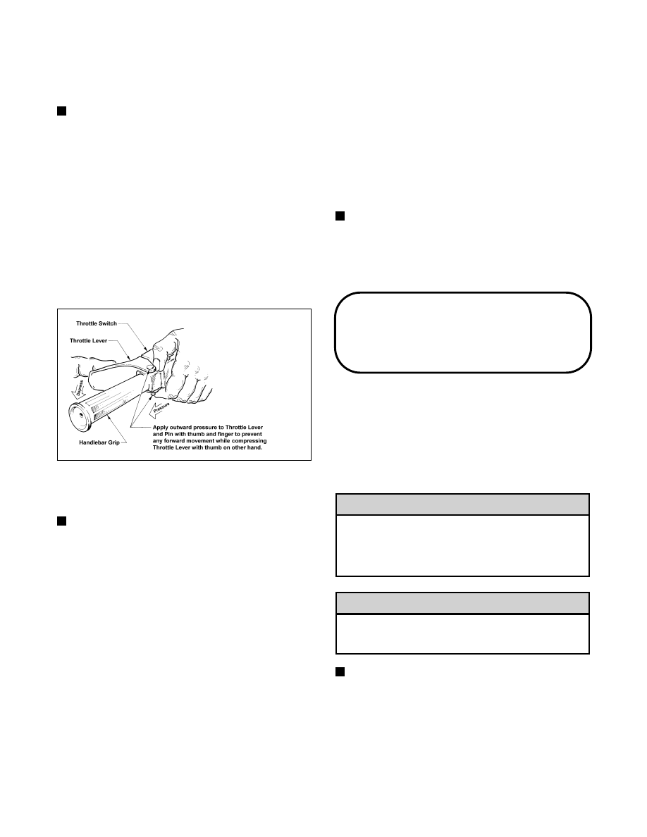
6. Hold both the top and bottom of the throttle lever
pin so that depression of the throttle lever does not
move the lever pin in its control slot.
Fig. 5-5
0728-916
7. Slowly depress the throttle lever to increase engine
RPM.
NOTE: It is very important that engine RPM be
allowed to increase slowly, since most engines have
a “rich area” at approximately 2500 RPM.
8. Observe the tachometer and the drive clutch to
determine the moment the carburetor safety
switches shut down the ignition. Since retaining the
throttle lever pin prevents the switch in the throttle
control housing from closing, the carburetor safety
switches should shut down the ignition at or
slightly after clutch engagement.
9. Repeat steps 6-8 several times. If ignition shutdown
a lway s o cc u r s a t o r s l i g h t l y af t e r cl u t ch
engagement, the carburetor safety switches are
synchronized.
10. Again, inspect the gap between the throttle lever
and the control housing at idle. Adjust the throttle
cable swivel adapter at the top of each carburetor
for 0.75-1.5 mm (0.030-0.060 in.) cable free-play
gap between the throttle lever “nibs” and the control
housing. While observing if there is any cable
free-play gap, apply slight pressure to the throttle
lever to take up any cable slack that may be present.
However, do not apply enough pressure to actually
raise the carburetor slides during this adjustment.
After cable free-play is properly adjusted, tighten
the jam nut on each carburetor securely.
NOTE: After completion of any adjustments,
throttle lever “side pressure” should not cause an
ignition miss at idle. Carburetor safety switches set
too low or an excessively tight throttle cable makes
the shutdown system very sensitive to throttle lever
“side pressure” near idle.
Troubleshooting
Ignition System
(Twin & Triple L/C Models)
When troubleshooting the standard “normally open”
ignition system, use the following procedure.
1. Remove the spark plugs and visually check their
condition. Replace any fouled plug. Attach the
spark plugs to the high tension leads and ground
them on the cylinder heads.
Before checking for spark, place all the engine
switches in the deactivated position. In the event
the engine could be flooded, pull the starter rope
(slowly at first) several times to clear the engine
of excess fuel.
Never crank the engine over without grounding
the spark plugs. Damage to coils and/or CDI unit
may result.
NOTE: Make sure the ignition switch and the
emergency stop switch are in the ON position.
2. Crank the engine over and check for spark. If no
spark is present, check to make sure the carburetor
throttle cables are properly tensioned. Compress
the throttle control and while holding the throttle
control in this position, crank the engine over and
check for spark. If spark is now present, adjust the
carburetor throttle cable tension.
! CAUTION
! CAUTION
5-18