Snowmobile Arctic Cat (2000 year). Manual - part 66
NOTE: The ignition system is a Normally Open Ignition (NOI).
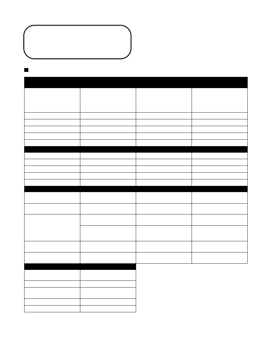
Description
Resistance Test
Test Value
+
Test Connections
-
Ignition Coil
Primary
Secondary
(Dual Lead)
(Single Lead)
0.29-0.39 ohm
6320-9480 ohms
6320-9480 ohms
positive spade terminal
high tension wire
high tension wire
negative spade terminal
high tension wire
positive spade terminal
Charge Coil (1)
16-24 ohms
green
black/red
Charge Coil (2)
360-540 ohms
green
white
Lighting Coil
0.12-0.18 ohm
yellow
yellow
Ignition Timing Sensor
80.8-121.2 ohms
green/white
brown
Spark-Plug Cap
4000-6000 ohms
cap end
cap end
Description
Peak Voltage Output Test (Arctic Cat Ignition Analyzer)
RPM
2000
3000
4000
Charge Coil (1)
190V
206V
175V
Charge Coil (2)
104V
142V
152V
CDI
137V
151V
148V
Lighting Coil
17V
20V
21V
Description
Test Value
+
Test Connections
-
Voltage Regulator
11-13 AC volts
@ 2500-2700 RPM
yellow
brown
Low Oil-Light Sending Unit
Less than 1 ohm
(float end down)
terminal
terminal
High Temperature Sensor
Open (water temperature
lower than 190°F)
terminal
ground
Up to 20 ohms (water
temperature higher than
230°F)
terminal
ground
High Temperature
Warning Light
Less than 10 ohms
terminal
terminal
Ignition Switch
Less than 1 ohm
(key in OFF position)
terminal
terminal
Description
Standard
Ignition Timing
27° BTDC @4000 RPM
3.884 mm (0.153 in.)
Lighting Coil Output
12V/210W
Ignition Type
CDI/NOI (Normally
Open Ignition)
Spark Plug
NGKBR9EYA
Spark-Plug Gap
0.7-0.8 mm (0.028-0.031 in.)
Electrical
Specifications
(600 cc Triple)
5-10