Snowmobile Arctic Cat (2000 year). Manual - part 48
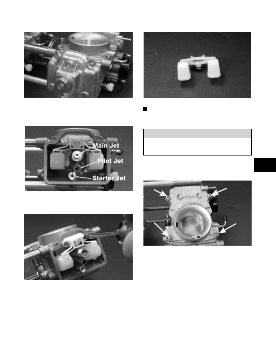
Fig. 4-37
AH618D
5. Remove the main jet (with washer), pilot jet, and
starter jet.
Fig. 4-38
AH619DA
6. Remove the screws securing the float assembly.
Fig. 4-39
AH620D
7. Remove the float assembly by lifting it up and out
of the mixing body. Account for the O-ring.
Fig. 4-40
AH621D
NOTE: It may be necessary to use a spray
lubricant such as WD-40 to aid in removing the float
assembly.
To remove the throttle valve, the jet needle must
be removed or damage to the jet needle will
result.
8. Remove the Phillips-head screws securing the
funnel assembly to the mixing body.
Fig. 4-41
AH622DA
9. Move the throttle lever to the full-open position;
then remove the funnel assembly. Account for the
gasket.
! CAUTION
4
4-11