Snowmobile Arctic Cat (2000 year). Manual - part 27


  Index      Snowmobiles / ATV     Snowmobile Arctic Cat - service manual 2000 year


Search            


Content   ..  25  26  27  28   ..


Snowmobile Arctic Cat (2000 year). Manual - part 27


Assembling Engine

(800/1000 cc Models)

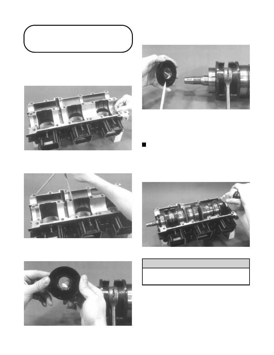
1. Set the top half of the crankcase on the work bench

with a wooden block under each end; then install
the seven bearing locating pins into the crankcase.

Fig. 2-396

AQ048

2. Install the two C-clips into the crankcase.

Fig. 2-397

AQ049

3. Apply bearing grease to the lips of the end seals.

Fig. 2-398

AQ050

4. Install the two end seals onto the crankshaft with

the spring side facing the bearing.

Fig. 2-399

AQ051

5. Set the crankshaft into the crankcase. Rotate each

bearing until its hole in the outer race drops onto the
locating pin. Check each bearing to make sure it is
properly positioned.

NOTE: To check the bearing for proper position,

place the point of a sharp tool into the dimple found
in the bearing race. Strike the tool with palm of the
hand in either direction. If the bearing moves, it isn’t
positioned correctly and must be rotated until it
drops onto the pin.

Fig. 2-400

AQ052

If the bearings are not properly seated during
assembly, the crankcase  halves  will not seal
tightly and severe engine damage will result.

6. The sealing rings must be located so none of the end

gaps align. Rotate the rings to “stagger” the end
gaps.

! CAUTION

2-92

Fig. 2-401

AQ053

7. Rotate the crankshaft while observing the timing

mark on the side of the gear. Align the timing mark
with the parting surface of the crankcase.

NOTE: Before installing the balancer shaft, pack

the bearings with grease. It is recommended that
Arctic Cat Low-Temp Grease (p/n 0636-593) be used
for this purpose.

Fig. 2-402

AQ054

8. Locate the timing mark on the balancer shaft gear;

then set the shaft into position aligning its timing
mark with the timing mark of the crankshaft gear.

Fig. 2-403

AQ055

9. Set the balancer shaft seal into position against the

bearing.

NOTE: Using Arctic Extreme 50:1 Injection Oil,

pre-oil the crankshaft and balancer shaft bearings
at this time.

Fig. 2-404

AQ056

10. Apply a light coat of High-Temp  Sealant (p/n

0636-069) to the sealing surface of the bottom half
of the crankcase. Make sure the entire surface is
coated evenly.

Fig. 2-405

AQ057

11. Place the bottom crankcase half into position and

install the twenty crankcase cap screws. Tighten the
cap screws evenly by hand starting in the center.
Tighten the cap screws in three steps to 4 kg-m (29
ft-lb). Follow the pattern shown.

Fig. 2-406

0729-590

2

2-93

12. Set the engine upright. Install the cylinder base

gasket making sure the small water passage hole is
positioned to the MAG-side.

NOTE: The cylinder base gasket can be reused if

not damaged. When reusing a gasket, coat each
side with Copper Coat Gasket Sealant (p/n
0636-092).

The cylinder base gasket must be installed with
the small water passage hole located  to  the
MAG-side of the crankcase or engine damage
will result.

Fig. 2-407

AQ030

13. Pre-oil the piston pin bearings and place into

position in the connecting rods; then place a thrust
washer on each end of the bearing. The flat side of
each washer must face outward.

Fig. 2-408

AQ059

14. Place the piston over the connecting rod so the

arrow on the piston dome will point towards the
exhaust port of the cylinder; then apply a light coat
of oil to the piston pin and install.

Fig. 2-409

AQ060

15. Install the piston rings on the piston with their

tapered side “up.”

16. Secure the piston pin by installing new piston pin

circlips. Install the circlip with the open end up.

Fig. 2-410

AQ080

17. Apply oil to the piston rings; then rotate the rings to

correctly position them on either side of the
locating pin in the ring groove. Place a short piece
of wear strip under the piston to keep it square; then
compress the piston rings with one hand and slide
the cylinder down onto the piston.

Fig. 2-411

AQ061

! CAUTION

2-94

18. Align the cylinder exhaust ports using a straight

edge; then secure each cylinder  base  with  four
washers, lock washers, and nuts. In three  steps
tighten the nuts to 4-6 kg-m (29-43 ft-lb). Use the
pattern shown.

Fig. 2-412

0729-585

19. Place the cylinder head O-rings into position on

each cylinder.

NOTE: If reusing O-rings and they are slightly

stretched, shrink the O-rings by cooling them (in a
refrigerator for example) for a period of time.

Fig. 2-413

AQ063

20. Being very careful not to move the two O-ring seals,

hold the cylinder head above the cylinder
approximately 1/4 in. and start the cap screws into
the cylinder;  then  check  the  O-rings for proper
position and set the head carefully down onto the
cylinder. Finger-tighten the cap screws at this time.

Fig. 2-414

AQ064

Be very careful not to move the cylinder heads
once they are placed on top of the O-rings.

21. Apply a thin coat of High-Temp Sealant (p/n

0636-069) to the three  water manifold gaskets.
Place the gaskets and manifold into position and
secure with  six cap screws.  Using  a  crisscross
pattern, tighten to 0.7-1 kg-m (5-7 ft-lb).

Fig. 2-415

AQ065

22. Tighten the cylinder head cap screws in three steps

using the pattern shown to 2-2.5 kg-m (14.5-18
ft-lb).

Fig. 2-416

0729-587

! CAUTION

2

2-95


Content   ..  25  26  27  28   ..