Snowmobile Arctic Cat (2000 year). Manual - part 19
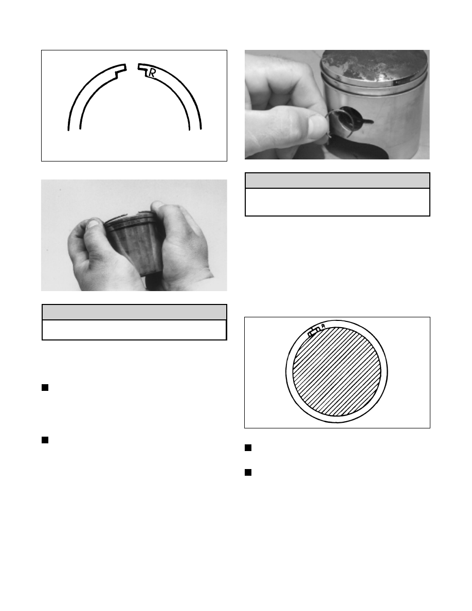
Fig. 2-254
726-306A
Fig. 2-255
AC088
Incorrect installation of the piston rings will
result in engine damage.
8. Apply oil to the connecting-rod small-end bearings;
then install the small-end bearings into the
connecting rods.
NOTE: Apply oil to the piston pin before installing.
9. Place each piston over the connecting rod so the
arrow on the piston dome points toward the exhaust
port; then secure with a piston pin.
NOTE: The arrow is found either up inside the
piston or on the dome top.
10. Install the new circlips so the open end is directed
either down or up.
Fig. 2-256
B324D
Make sure circlips are firmly seated and the open
end is directed either down or up before
continuing with assembly.
11. Install the cylinder base gaskets onto the crankcase
making sure each gasket aligns with crankcase
transfer passages.
12. Rotate each piston ring until the ring ends are
properly positioned on each side of the ring keeper;
then apply oil to the piston assemblies and cylinder
bores. Remove the rubber bands from the connecting
rods.
Fig. 2-257
726-306B
NOTE: Apply a generous amount of oil to the
surfaces of the pistons, rings, and cylinder bores.
NOTE: Inspect the cylinder-base gasket to ensure
proper positioning.
13. For each piston, place a piston holder (or suitable
substitute) beneath the piston skirt and square the
piston in respect to the crankcase; then using a ring
compressor or the fingers, compress the rings and
slide the cylinder over the piston. Remove the piston
holder and seat the cylinder firmly onto the
crankcase.
! CAUTION
! CAUTION
2-60