Snowmobile Arctic Cat (2000 year). Manual - part 17


  Index      Snowmobiles / ATV     Snowmobile Arctic Cat - service manual 2000 year


Search            


Content   ..  15  16  17  18   ..


Snowmobile Arctic Cat (2000 year). Manual - part 17


4. Position the indicator contact point  against the

crankshaft at point E (center). Zero the indicator
and rotate the crankshaft slowly. Note the amount
of crankshaft runout (total indicator reading).

CRANKSHAFT RUNOUT (max)

(total indicator reading)

mm

in.

0.05

0.002

5. If runout exceeds specifications at any of the

checkpoints, the crankshaft must be either
straightened or replaced.

1999

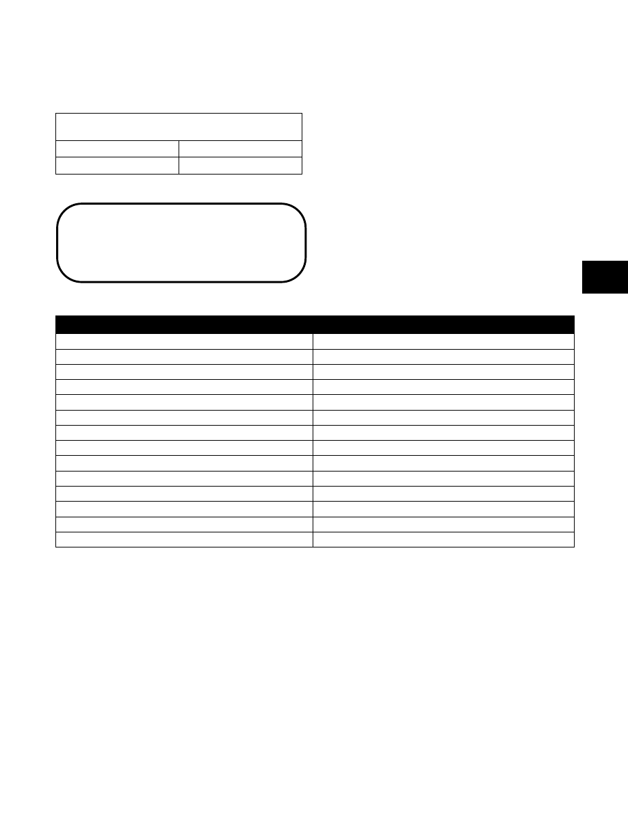
Engine Specifications

(60 cc)

ITEM

SPECIFICATIONS

Model

AP06A2

Type

2 Cycle, Air-Cooled

No. of Cylinders

1

Bore x Stroke

41 x 45 mm (1.614 x 1.772 in.)

Displacement

59 cc (3.6 cu in.)

Compression Ratio

6.6:1

Cylinder Trueness (max)

0.1 mm (0.004 in.)

Piston Ring End Gap Range

0.1-0.8 mm (0.004-0.031 in.)

Piston Skirt/Cylinder Clearance Range

0.07-0.15 mm (0.0028-0.0059 in.)

Piston Pin Diameter Range

11.996-12.000 mm (0.4723-0.4724 in.)

Piston Pin Bore Diameter Range

12.000-12.010 mm (0.4724-0.4728 in.)

Connecting Rod Small End Diameter Range

16.003-16.011 mm (0.6300-0.6304 in.)

Crankshaft Runout (max)

0.05 mm (0.002 in.)

Crankshaft End Play Range

0.05-0.10 mm (0.002-0.004 in.)

2

2-51

Assembling Engine

Table of Contents

60 cc Model . . . . . . . . . . . . . . . . . . . 2-53
F/C Models . . . . . . . . . . . . . . . . . . . 2-58
440 LC/550 cc Models . . . . . . . . . . . . . 2-64
500/580/600 cc Twin Models . . . . . . . . . . 2-70
700 cc Models . . . . . . . . . . . . . . . . . 2-76
600 cc Triple Models . . . . . . . . . . . . . . 2-85
800/1000 cc Models . . . . . . . . . . . . . . 2-92

Assembling Engine

(60 cc Model)

CRANKCASE/GEAR CASE

1. If the bearings were removed, install the bearings

into the crankcase halves.

2. Using a seal installing tool, insert the seals into the

crankcase halves.

NOTE: Make sure the spring side of seal is

positioned toward the center of the crankshaft.

3. Apply grease to the inner lips of the seals.

Fig. 2-217

A744

4. Press the crankshaft into MAG-end of case.

Fig. 2-218

A742

5. Apply High-Temp Sealant (p/n 0636-069) to one

half of the crankcase.

Fig. 2-219

A743

6. If removed, install crankcase dowel pins.

7. Apply blue Loctite #242 to the five crankcase cap

screws; then assemble the crankcase. Tighten to
0.6-1 kg-m (4.5-7 ft-lb).

Fig. 2-220

A745

NOTE: Place a rubber band over the connecting

rod to prevent the rod from damaging the crankcase
if the crankshaft is accidentally rotated.

8. Install the key in the PTO-end of the engine

crankshaft. Slide the drive gear onto crankshaft so
the large beveled edge is positioned inward.

2

2-53

Fig. 2-221

A746

9. Place the centrifugal onto the PTO-end of crankshaft

making sure the notch of the centrifugal aligns with
keyway of the crankshaft.

Fig. 2-222

A747

10. Secure the PTO-end crankshaft components by

applying blue Loctite #242 to the nut, installing the
PTO-end nut, and tightening the nut to 3-4 kg-m
(22-29 ft-lb).

Fig. 2-223

A749

11. Install the  shifter  so the  centrifugal  weights are

positioned against the shifter arms.

Fig. 2-224

A750

12. Install the bearing in the gear case housing. Apply

grease to the inner lips of the seal; then place the seal
into position.

Fig. 2-225

A751

13. Install the primary driven shaft.

Fig. 2-226

A752

14. Apply High-Temp Sealant (p/n 0636-069) to both

sides of the gear case gasket. Place the gasket against
the crankcase.

2-54

Fig. 2-227

A753

15. Install the gear case cover with output shaft. Install

the five screws; then tighten the screws with an
impact screwdriver.

Fig. 2-228

A755

CYLINDER HEAD/FAN

16. Place the bearing in the connecting rod small end.

Apply Arctic Cat 50:1 Injection Oil to the bearing.

Fig. 2-229

A767

17. Install the piston rings. The letter near the ring end

must be positioned upward. Make sure ring ends are
positioned correctly over piston ring keepers.

Fig. 2-230

A736

18. Place the piston assembly onto the connecting rod.

Make sure the arrow on dome of the piston points to
the exhaust side of the engine.

Fig. 2-231

A768

19. Install the piston pin. Secure the piston pin with

circlips.

Fig. 2-232

A776

NOTE: Make sure the open ends of the circlips are

directed toward either the piston top or bottom.

20. Apply a thin coat of high temperature sealant to both

sides of the cylinder base gasket; then install the base
gasket.

2

2-55


Content   ..  15  16  17  18   ..