Snowmobile Arctic Cat (2000 year). Manual - part 16


  Index      Snowmobiles / ATV     Snowmobile Arctic Cat - service manual 2000 year


Search            


Content   ..  14  15  16  17   ..


Snowmobile Arctic Cat (2000 year). Manual - part 16


4. Inspect the oil-injection pump drive gear for any

signs of worn or chipped teeth. If either condition
exists, replace the gear.

Fig. 2-201

AQ043

NOTE: Lubricate bearings thoroughly  prior to

assembly.

REMOVING OUTER
CRANKSHAFT BEARINGS

! WARNING

Safety glasses must be worn when spreading
bearings.

NOTE: Steps 1-3 are for removing the MAG-side

bearing.

1. Place a bearing support (block of wood, etc.)

beneath the MAG-side bearing.

A bearing support must be positioned beneath
the bearing that is being removed to prevent
crankshaft damage.

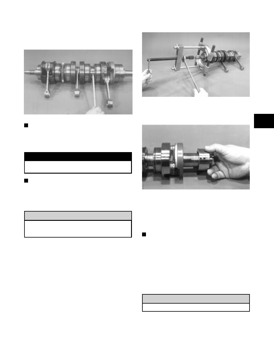
2. Drive a chisel or bearing splitter between the

bearing race and crankshaft counterweight until the
bearing is spread far enough to install the jaws of
the crankshaft bearing remover.

3. Place the protective cap on the crankshaft end; then

using the Crankshaft Bearing Remover (p/n
0144-302), remove the bearing from the end of the
crankshaft. Account for any shim(s). Note the
position of the dowel pin hole.

Fig. 2-202

AQ045

4. The PTO-side bearing may be removed simply by

sliding the bearing off the PTO end.

Fig. 2-203

AN151A

5. Inspect the crankshaft bearing area for wear. If any

wear is noted on either end, replace the crankshaft
end.

INSTALLING OUTER
CRANKSHAFT BEARINGS

NOTE: Steps 1-3 are for installing the MAG-side

bearing.

1. Wrap a thick towel around the crankshaft; then

secure the crankshaft vertically in a vise.

2. Heat the bearing either by placing the entire bearing

in a pan of oil on a hot plate or by squirting oil into
the bearing and using a propane torch to heat the
inner race of the bearing until a slight smoke is
noted coming from the bearing.

DO NOT overheat the bearing.

! CAUTION

! CAUTION

2

2-47

3. Place any shims removed during disassembly onto

the crankshaft; then slide the bearing onto the
crankshaft making sure the dowel-pin hole in the
outer race is properly positioned and will align with
its hole and pin in the crankcase.

4. Slide the PTO-side bearing  onto  the PTO  end

making sure the dowel-pin hole will align with the
hole and pin in the crankcase.

Fig. 2-204

AN151A

BALANCER SHAFT (800/1000 CC)

1. Inspect the balancer shaft bearings by rotating them

by hand. The bearings must rotate freely without
binding or feeling rough. If either condition exists,
replace the bearing. Inspect the balancer gear very
closely for any chipped teeth or signs of wear. If
either condition exists, replace the gear.

Fig. 2-205

AQ044

REED ASSEMBLY

1. Inspect the reed valves, stoppers, and valve blocks

for cracks or any deterioration.

Fig. 2-206

AQ046

2. Wash the reed valves, stopper, and cage assembly in

parts-cleaning solvent and blow dry.

3. Inspect the reed stopper height. Using a caliper,

measure the distance from the seat to the bottom
outer tip edge of the stopper. Measurement must not
exceed specifications. If measurement is not within
specifications, either bend or replace the reed
stopper.

Fig. 2-207

AJ156

4. Inspect the reed-to-seat clearance. Using a feeler

gauge, measure the clearance. Clearance must be
less than 0.20 mm (0.008 in.). If clearance is not
within specifications, replace the reed valve.

5. To assemble, place the reed valves on the cage with

its clipped corner positioned to the lower right hand
corner of the cage. Place the reed stopper assembly
into position  and  secure with  the three screws
coated with red Loctite #271.

2-48

Fig. 2-208

AQ047

Measuring Critical

Components

NOTE: Critical engine component specifications

are on pages 51-52 of this section.

CYLINDER TRUENESS

1. Measure each cylinder in the three locations from

front to back and side to side for a total of six readings.

Fig. 2-209

AN302

2. The trueness (out-of-roundness) is the difference

between the highest and lowest reading. Maximum
trueness (out-of-roundness) must not exceed
specifications.

Fig. 2-210

0725-586

CYLINDER TRUENESS LIMIT (max)

mm

in.

0.10

0.004

PISTON SKIRT/CYLINDER CLEARANCE

1. Measure each cylinder front to back about 2.5 cm

(1 in.) from the bottom of each cylinder.

2. Measure the corresponding piston skirt diameter at

a point 1 cm (0.394 in.) above the piston skirt at a
right angle to the piston-pin bore. Subtract this
measurement from the measurement in step 1. The
d i ff e r e n c e

( c l ea r a n ce )

m u s t

b e

w i t h i n

specifications.

Fig. 2-211

AC091

PISTON-RING END GAP

1. Place each piston ring in the wear portion above the

exhaust  port  of its  respective cylinder. Use  the
piston to position each ring squarely in each
cylinder.

2. Using a feeler gauge, measure each piston-ring end

gap. Acceptable ring end gap must be within
specifications.

2

2-49

Fig. 2-212

AN057

PISTON PIN AND PISTON-PIN BORE

1. Measure the piston pin diameter at each end and in

the center.  Acceptable piston pin measurement
must be within specifications. If any measurement
varies by more than 0.02 mm (0.001 in.), the piston
pin and bearing must be replaced as a set.

Fig. 2-213

AN056

2. Insert a snap gauge into each piston-pin bore; then

r e m ove t h e g a u g e a n d m e as ur e i t w i t h a
micrometer. The diameter measurement must be
within specifications. Take two measurements to
ensure accuracy.

Fig. 2-214

AC092

CONNECTING-ROD SMALL END BORE

1. Insert a snap gauge into each connecting-rod small

end bore; then remove the gauge and measure it
with a micrometer.

Fig. 2-215

AN061

2. The diameter measurement

must be within

specifications.

CRANKSHAFT RUNOUT

1. Using the V Blocks (p/n 0644-022), support the

crankshaft on the surface plate.

N OT E : T h e V bl ocks sh o ul d s up p or t t h e

crankshaft on the outer bearings.

2. Mount a dial indicator and base on the surface plate.

Position the indicator contact point  against the
crankshaft distance F (PTO-end) from the
crankshaft end. Zero the indicator and rotate the
crankshaft slowly. Note the amount of crankshaft
runout (total indicator reading).

NOTE: For  runout distance  specifications, see

pages 143-144 of this section.

3. Position the indicator contact point  against the

crankshaft distance D (MAG-end) from the
crankshaft end. Zero the indicator and rotate the
crankshaft slowly. Note the amount of crankshaft
runout (total indicator reading).

Fig. 2-216

AQ042

2-50


Content   ..  14  15  16  17   ..