Snowmobile Arctic Cat (2000 year). Manual - part 14


  Index      Snowmobiles / ATV     Snowmobile Arctic Cat - service manual 2000 year


Search            


Content   ..  12  13  14  15   ..


Snowmobile Arctic Cat (2000 year). Manual - part 14


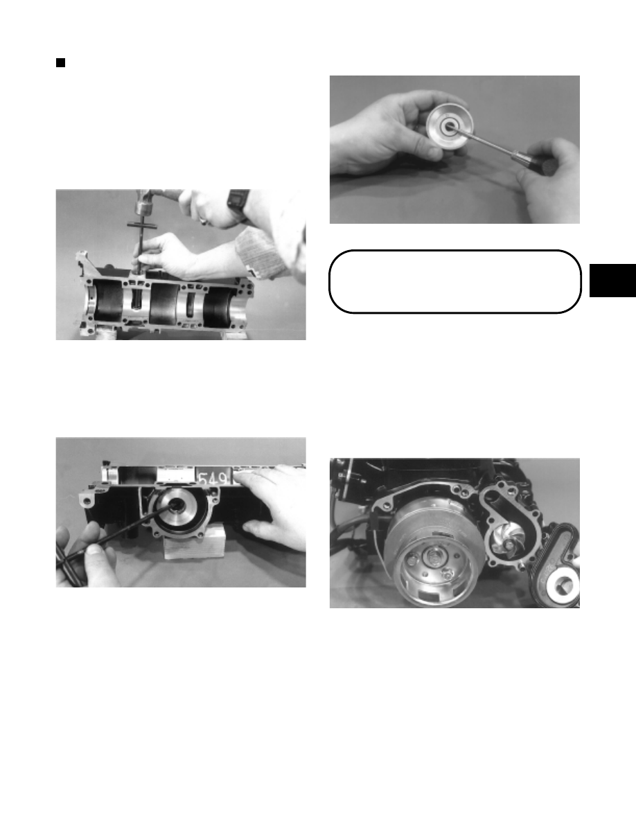
NOTE: Do not replace the inner oil seal or

mechanical seal unless the water pump shows
signs of leaking coolant out of the small bleed hole
in the bottom half of the crankcase. If a water pump
seal is to be replaced, use the Water Pump Bearing
and Seal Kit (p/n 0644-084).

33. Place the crankcase on the bench with the water

pump side down. Using the long seal driver, drive
the water pump seal from the crankcase.

Fig. 2-169

AN226

34. Using a pair of snap ring pliers, remove the snap

ring securing the inner seal in the crankcase.

35. Using the hooked end of the seal driver, pull the

inner seal free of the crankcase.

Fig. 2-170

AN224

36. Using a sharp-pointed tool, pry the seal ring from

the backside of the water pump impeller.

Fig. 2-171

AN051

Disassembling Engine

(800/1000 cc Models)

1. Using an impact driver or a 6-mm hex wrench,

remove the four cap screws securing the magneto
housing to the crankcase. Account for the alignment
dowels.

2. Using an impact driver, remove the five screws

securing the water pump cover. Remove the cover
and account for the O-ring  seal and alignment
dowels.

Fig. 2-172

AQ005

3. Secure the crankshaft using a spanner wrench; then

remove the cap screw securing the water pump
impeller.

2

2-39

Fig. 2-173

AQ006

4. Remove the water pump impeller from the

counterbalance shaft.

5. With the impeller removed, check the condition of

the seal on the back side. It must be free of any
cracks, chips, or rough areas.

NOTE: If any rough areas are found, the seal ring

can be removed using a small screwdriver. Simply
pry the seal ring upward; then remove the rubber
cup from beneath the seal ring.

Fig. 2-174

AQ008

6. Remove the remaining water pump center and back

section from the counterbalance shaft.

7. Inspect the front mechanical seal and rear  seal

surface for any rough areas. If the seals need
replacement, see the appropriate Repairing Water
Pump in Section 3.

Fig. 2-175

AQ010

8. Using a spanner wrench to secure the crankshaft,

remove the cap screw, lock washer, and large flat
washer securing the flywheel.

9. Remove the three cap screws securing the starter

pulley to the flywheel.

10. To prevent damaging the crankshaft threads during

the flywheel removal procedure,  use the  Puller
Insert (p/n 0644-179) on the end of the crankshaft.

Fig. 2-176

AQ019

11. Attach the flywheel puller to the flywheel using

three 8-mm cap screws approximately 2 3/4 in.
long. Thread each of the three cap screws evenly
into the flywheel 1/2 in.

12. Tighten the center puller bolt against the insert on

the crankshaft. Continue to tighten the puller bolt
until the flywheel snaps free of the crankshaft taper.
Remove the puller from the flywheel and place the
flywheel, open side up, on a clean work bench.
Account for the flywheel key.

2-40

Fig. 2-177

AQ020

13. Remove the Allen-head cap screws securing the

stator to the stator plate.

14. Remove the rubber grommet from the crankcase

and slide the stator free of the crankshaft.

Fig. 2-178

AQ021

15. Remove the three Allen-head cap screws securing

the stator plate to the crankcase.

16. Remove the  thermostat  cover;  then remove the

thermostat from the water manifold.

NOTE: The thermostat is designed to open at 50°C

(122°F). It should be checked for proper operation
before installing (see Section 3).

17. Remove the water manifold assembly.

18. Remove the heads from the cylinders. Account for

the two O-rings under each head.

19. For assembly purposes, number the three heads and

cylinders. Start from the MAG-side.

Fig. 2-179

AQ026

20. Remove the four nuts, lock washers, and flat

washers securing each cylinder to the crankcase;
then carefully lift each cylinder straight up and free
of the piston. Support the piston as the cylinder
clears the piston to prevent the connecting rod from
dropping against the crankcase and causing damage
to the crankcase sealing surface.

Fig. 2-180

AQ027

21. For assembly purposes, number the dome of each

piston starting from the MAG-side; then remove the
MAG-side circlip from each piston.

Fig. 2-181

AQ028

2

2-41

22. Using Piston Pin Puller (p/n 0644-328), remove the

piston pin from each piston. Remove the piston,
piston pin bearing, and the two shim washers. Keep
each piston, piston pin, and bearing together as a
set.

Fig. 2-182

AQ029

23. Before lifting the cylinder base gasket from the

crankcase, note how it is installed. The smaller of
the three water passage holes must be positioned to
the MAG-side of the crankcase when installing.
Lift the gasket free of the crankcase.

NOTE: If the cylinder base gasket is not damaged,

it can be reused.

Fig. 2-183

AQ030

24. Remove the two screws securing the oil-injection

pump to the crankcase. Slide the pump free of the
crankcase. Account for the O-ring located around
the pump inner flange.

25. Remove the pump retainer and shaft. Account for

the shaft thrust washer.

Fig. 2-184

AQ119

26. Remove  the  six cap screws securing the  intake

flanges and reed valve assembly to the crankcase.

27. Remove the intake flange and reed valve assembly.

Be very careful not to damage the reed valve stops.
Place the assembly on its flat side. Remove and
discard the reed valve assembly gasket.

Fig. 2-185

AN236

28. Using an impact driver, remove the four screws

securing the PTO-end plate to the end of the
crankcase; then slide the plate free of the
crankshaft.

Fig. 2-186

AQ034

29. Remove the twenty cap screws securing the two

crankcase halves together.

2-42


Content   ..  12  13  14  15   ..