Snowmobile Arctic Cat (2000 year). Manual - part 12
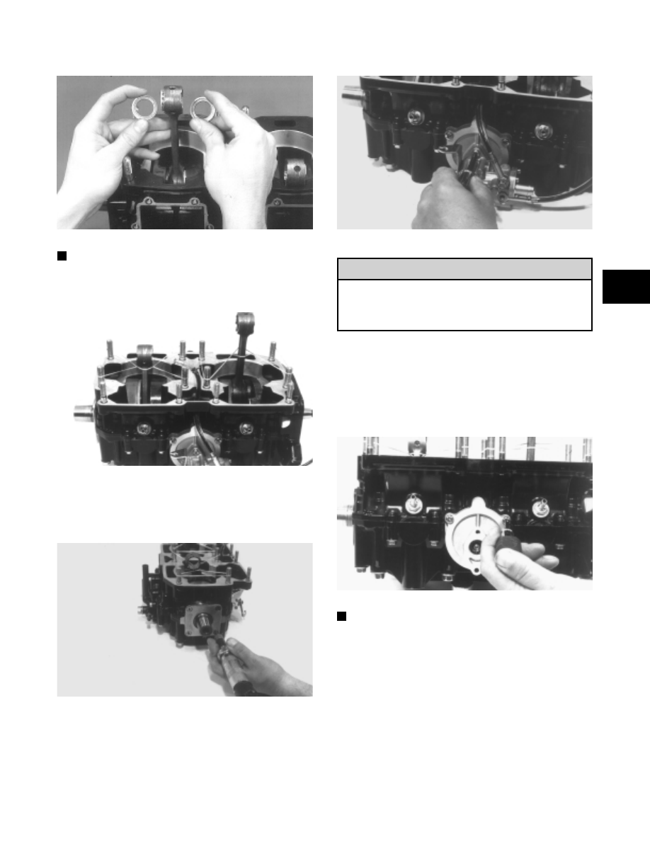
Fig. 2-128
AQ059
NOTE: Place rubber bands over the connecting
rods and around the cylinder studs. This will keep
the connecting rods from damaging the crankcase.
Fig. 2-129
AJ031
21. Using an impact driver, remove the four screws
securing the PTO-end plate to the crankcase; then
remove the plate.
Fig. 2-130
AJ032
22. Remove the two screws and lock washers securing
the oil-injection pump to the crankcase.
Fig. 2-131
AJ035
Note that the shorter of the two screws securing
the oil pump to the crankcase came from the top
mounting hole of the oil-injection pump. It must
be installed in the same location.
23. Remove the two screws securing the oil-injection
pump retainer to the crankcase. Gently tap on the
retainer with a plastic hammer to free it from the
crankcase. Pull the retainer straight back and free of
the crankcase. Account for the O-ring found around
the inner flange of the retainer sealing surface.
Fig. 2-132
AJ036
NOTE: Account for the shim washer(s) found on
the upper pinion driven shaft. If no shim(s) are
found on the shaft, check the retainer just removed
as they will sometimes stick to the bearing race.
Remove shim(s) and place in a safe place where
they won’t be lost.
24. Remove the five cap screws securing the water
pump cover to the crankcase. Remove the cover and
O-ring seal.
! CAUTION
2
2-31