Snowmobile Arctic Cat (2000 year). Manual - part 10
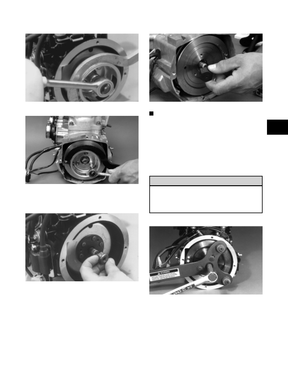
Fig. 2-91
AN015
Fig. 2-92
AN407D
2. Install the Crankshaft Protector Cap (p/n 0644-234)
onto the end of the crankshaft.
Fig. 2-93
AN018
Fig. 2-94
AN408D
NOTE: A suitable substitute protective cap can be
made by welding a 3 mm (1/8 in.) plate on one side
of a spare flywheel nut.
3. Using the Flywheel Puller/Spanner Wrench (p/n
0144-310) or suitable substitute, remove the
flywheel from the crankshaft by tightening the
puller bolt, striking the head of the puller bolt with
a hammer, and tightening again. Repeat this
procedure until the flywheel is free. Account for the
key.
To prevent damage to the crankshaft, the puller
must bottom on the cap and not on the
crankshaft. Also, do not thread puller bolts more
than 12.7 mm (1/2 in.) into the flywheel. Damage
to the coils may result.
Fig. 2-95
AR105
! CAUTION
2
2-23