Snowmobile Arctic Cat (2000 year). Manual - part 7
14. Loosen the clamp securing the coolant supply hose
to the water pump housing; then remove the hose
from the water pump. Loosen the clamp securing
the hose to the thermostat cap; then remove the hose
from the cap.
15. Disconnect the temperature-gauge sender wire.
Fig. 2-38
AJ663
16. Remove the cap screws securing the engine
mounting brackets to the front end. Account for
mounting hardware.
17. Lift the MAG-side of the engine. Remove the four
cap screws and lock washers securing the recoil
starter; then remove the starter from the engine.
Leave it in the engine compartment.
Fig. 2-39
AN012
18. Lift the engine with engine mounting brackets out
of the engine compartment.
19. Remove the mounting brackets from the crankcase.
Disassembling Engine
Table of Contents
60 cc Model . . . . . . . . . . . . . . . . . . . 2-11
F/C Models . . . . . . . . . . . . . . . . . . . 2-16
440 LC/550 cc Models . . . . . . . . . . . . . 2-19
500/580/600 cc Twin Models . . . . . . . . . . 2-22
700 cc Models
. . . . . . . . . . . . . . . . . 2-27
600 cc Triple Models
. . . . . . . . . . . . . . 2-34
800/1000 cc Models
. . . . . . . . . . . . . . 2-39
Disassembling Engine
(60 cc Model)
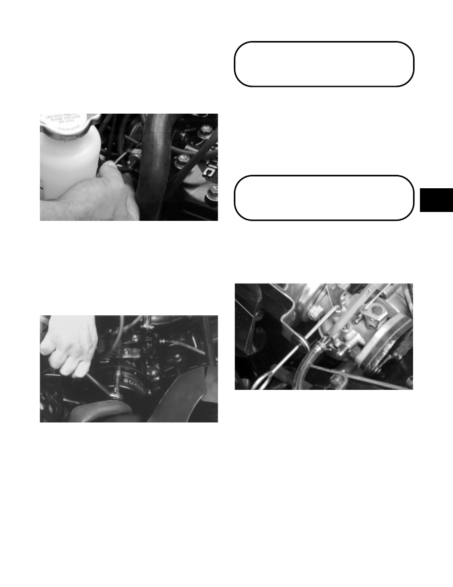
FUEL TANK/CLUTCH
1. Remove the fuel supply hose from the carburetor
body.
Fig. 2-40
A955
2. Loosen the machine screw securing the fuel tank
bracket to the recoil starter housing; then remove
the two machine screws securing the fuel tank
bracket to the cylinder head and remove the fuel
tank assembly.
2
2-11