Snowmobile Arctic Cat (2000 year). Manual - part 6


  Index      Snowmobiles / ATV     Snowmobile Arctic Cat - service manual 2000 year


Search            


Content   ..  4  5  6  7   ..


Snowmobile Arctic Cat (2000 year). Manual - part 6


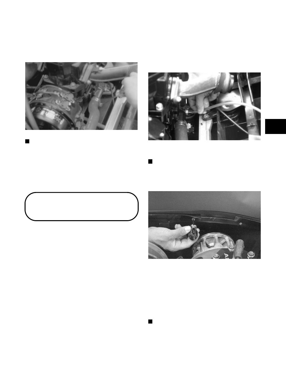
18. Raise the engine up slightly; then loosen the clamp

securing the supply hose to the water pump housing
and remove the hose from the water pump. Loosen
the clamp securing the hose to the thermostat cap;
then remove the hose from the cap.

Fig. 2-22

AN143

NOTE: Inspect the engine to ensure all wires,

hoses, and cables have been removed.

19. Lift the engine with mounting brackets out of the

engine compartment.

20. Remove the cap screws securing the engine

mounting brackets to the crankcase; then remove
the brackets.

Removing Engine

(550 cc Models)

1. Disconnect the battery cables making sure to

disconnect the negative cable first.

2. Turn the gas tank shut-off valve to the CLOSED

position.

3. Remove the cable tie and positive battery cable

from the starter motor.

4. On the Wide  Track, remove  the  two lock nuts

securing the starter motor to the engine mounting
bracket; then place the starter motor and end cap off
to the side.

5. Remove the springs securing the expansion

chamber to the exhaust manifold, front end, and
resonator. Remove the expansion chamber and
grafoil gasket.

6. Attach a  long piece of fuel  hose to  the engine

coolant drain (located on the exhaust side of the
engine). Route the hose outside the engine
compartment and into a container. Open the drain
and remove the filler cap. Once the coolant stops
flowing,  remove the  hose  and  tighten  the  drain
valve.

Fig. 2-23

AP058

7. Open the belt guard: then remove the drive belt.

NOTE: On the Wide Track, remove the machine

screws securing the side panel to the belly pan;
then remove the side panel. On the Panther 550 and
ZL 550, remove the rubber plug from the belly pan.

Fig. 2-24

AM115D

8. Using a ½-in. twelve-point socket, remove the bolt

and lock washer securing the drive clutch to the
crankshaft. Using the Clutch Puller (p/n 0644-207)
and an impact wrench or a breaker bar and the
Flywheel Pulley/Spanner Wrench (p/n 0144-310),
tighten the puller. If the drive clutch will not release,
sharply strike the head of the puller. Repeat this step
until the clutch releases. Remove the drive clutch.
If applicable, account for the two sleeves.

NOTE: On the Wide Track, remove the lock nut

securing the belly pan and bumper to the bumper
support tube; then remove the rear plug from the
belly pan.

2

2-7

Fig. 2-25

AF459D

9. Remove the cap screw and washer securing the

driven pulley; then slide the driven pulley off the
driven  shaft.  Account for a  key  and alignment
washers.

Fig. 2-26

AF120D

NOTE: If the driven pulley is tight on the driven

shaft, pull the driven pulley off using the Driven
Pulley Puller (p/n 0744-023).

10. Loosen the flange clamp securing each carburetor

to its flange; then remove the carburetors. Position
the carburetors to one side in an upright position.

Fig. 2-27

AJ172

11. Disconnect the impulse hose from the crankcase.

12. Remove the cable tie securing the engine and CDI

wiring harnesses to the engine; then disconnect the
main  wiring harness  from  the engine and CDI
wiring harnesses.

13. Remove the spark  plug  caps and the cable tie

securing the temperature-gauge sender wire; then
disconnect the sender wire.

14. On the Wide Track, remove the ground wire from

the magneto housing.

15. Remove the E-clip and washer securing the

oil-injection cable; then disconnect the oil-injection
cable from the pump. Disconnect the oil-supply
hose from the pump and plug the hose to prevent oil
drainage.

Fig. 2-28

AN009

16. Loosen the clamp securing the supply hose to the water

pump housing; then remove the hose from the water
pump. Loosen the clamp securing the hose to the
thermostat cap; then remove the hose from the cap.

17. Remove the  four  cap screws  and  lock washers

securing the recoil starter; then remove the starter
f r o m t h e e n g i n e . L e ave i t i n t h e en g i n e
compartment.

NOTE:

On the Panther 550, account for the

ground wire.

18. Support the hood; then remove the hood cable from

the exhaust manifold.

19. Remove the mounting hardware securing the

engine to the front end.

NOTE: On the Wide Track, account for shims and

note their position on the left rear engine mount for
assembly purposes.

2-8

Fig. 2-29

AR321

Fig. 2-30

AN013

20. Lift the engine with mounting brackets out of the

engine compartment.

Do not use the starter motor shaft to lift the
engine. Damage may occur.

21. Remove the engine mounting brackets.

Removing Engine

(Triple Models)

1. Turn the gas tank shut-off valve to the CLOSED

position.

Fig. 2-31

AL658D

2. Secure the hood with  a hold-down  strap; then

remove the hood cable.

3. Remove the springs securing the expansion

chambers to the header pipes, the front end, and the
resonator. Remove the  expansion  chambers  and
three grafoil gaskets.

NOTE: Number the expansion chambers before

removing to aid in assembly.

4. Remove the  cap screws securing  the resonator.

Account for and note the location of the engine
ground cable with star washer, washers, bushings,
spacers, and retaining nuts.

5. Attach a  long piece of fuel  hose to  the engine

coolant drain. Route the hose outside the engine
compartment and into a container. Open the drain
valve; then remove the coolant filler cap to vent the
system. Once the coolant stops flowing, remove the
hose and tighten the drain valve.

Fig. 2-32

AQ123

6. Open the belt guard; then remove the drive belt.

! CAUTION

2

2-9

7. Remove the plug from the belly pan; then using a

1/2 in. twelve-point socket, remove the bolt and
lock washer securing the drive clutch to the
crankshaft.  Using  the Drive Clutch  Puller  (p/n
0644-207) and an impact wrench or a breaker bar
and Spanner Wrench (p/n 0644-136), tighten the
puller. If the drive clutch will not release, sharply
strike the head of the puller. Repeat this step until
the clutch releases. Remove the drive clutch. If
applicable, account for the two sleeves.

Fig. 2-33

AF472D

8. Remove the cap screw securing the driven pulley;

then slide the driven pulley off the driven shaft.
Account for a stub shaft, the location of all washers,
and a key.

Fig. 2-34

SC013D

NOTE: If the driven pulley is tight on the shaft, pull

the driven pulley off using the Driven Pulley Puller
(p/n 0744-023).

9. Label  the carburetors.  Loosen  the flange  clamp

securing each carburetor to its flange; then remove
the carburetors from the intake flanges. Position the
carburetors to one side in an upright position.

Fig. 2-35

AN614D

10. Disconnect the impulse hose from the crankcase.

11. Loosen the engine torque bumper; then remove the

left-side rear engine nut and washer.

Fig. 2-36

AN610D

12. Disconnect the engine and timing sensor wiring

harnesses from the main wiring harness. Remove
the spark-plug caps from the spark plugs. Remove
the cap screw securing the two ground wires to the
magneto housing cover.

13. Remove the E-clip and washer securing the

oil-injection cable; then disconnect the oil-injection
cable from the oil-injection pump. Disconnect the
oil-supply hose and the oil-output hose from the
pump and plug the hoses to prevent oil drainage.

Fig. 2-37

AN392D

2-10


Content   ..  4  5  6  7   ..