Snowmobile Polaris Power P1000i, P2000i (2018 year). Manual - part 6
21
OPERATION
Total Running (Rated) Watts = 660
Additional Starting Surge Watts = 1380
Total Generator Output Required = 2040
Ensure the combined electrical rating of the powered
device(s) do not exceed the maximum allowed by the
generator. Never exceed the maximum power rating
of the generator. Power levels between rated and
maximum may be used for no more than 30 minutes.
DC Operation
Connecting the Battery Charging Cable:
The battery emits explosive hydrogen gas during
normal operation. A spark or flame can cause the
battery to explode with enough force to kill or cause
serious injury. Wear protective clothing and eye
protection when charging a battery.
Battery posts, terminals, and related accessories
contain lead and lead components. Wash hands after
handling.
The DC charging output is not regulated. The DC
receptacle should only be used for charging 12Vdc
batteries.
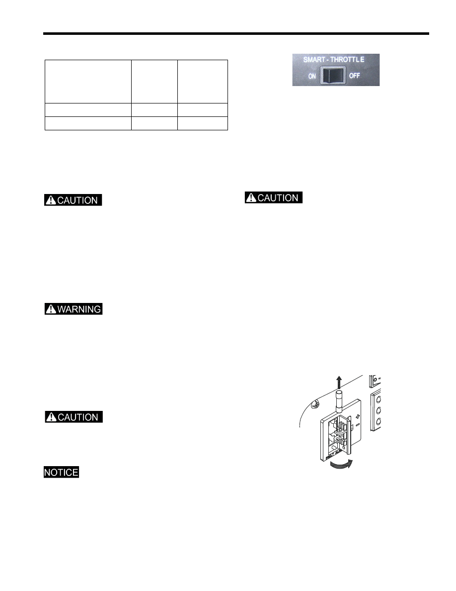
When using the DC output, position the SMART throttle
switch to OFF.
The DC receptacle may be used while the AC power is
in use.
1.
Position the SMART throttle switch to OFF.
2.
Disconnect the vehicle ground cable from the
negative (-) battery terminal.
3.
Plug the battery charging cable into the DC receptacle
(see “Controls and Features, Control Panel”).
4.
Connect the red lead of the battery charging cable to
the positive (+) battery terminal and then the black
lead to negative (-) battery terminal.
Start the generator.
Do not start the vehicle while the battery charging
cable is connected and the generator is running. The
vehicle’s charging system or the generator may be
damaged.
An overloaded DC circuit, excessive current draw by
the battery, or a wiring problem will trip the DC circuit
fuse. If this happens, The fuse must be replaced
before the DC receptacle is operative. Replace the
fuse with one of the same size and rating (5 amp).
Exceeding the current rating may lead to alternator
damage. If the DC circuit protector fuse continues to
trip, discontinue charging and see your authorized
Polaris generator dealer.
The circuit protector does not prevent overcharging
the battery. Over charging the battery may result in
battery damage and potential ignite if a spark is
introduced.
Disconnecting the Battery Charging Cable:
1.
Stop the generator.
2.
Disconnect the black lead of the battery charging
cable from the negative (-) battery terminal and then
the lead from the positive (+) battery terminal.
Power Management
DEVICE
RUNNING
(RATED)
WATTS
ADDITIONAL
STARTING
(SURGE)
WATTS
Paint Sprayer
360
1080
Radio
300
300