Snowmobile Polaris DEEP SNOW (2005 year). Manual - part 67
ELECTRICAL
13.25
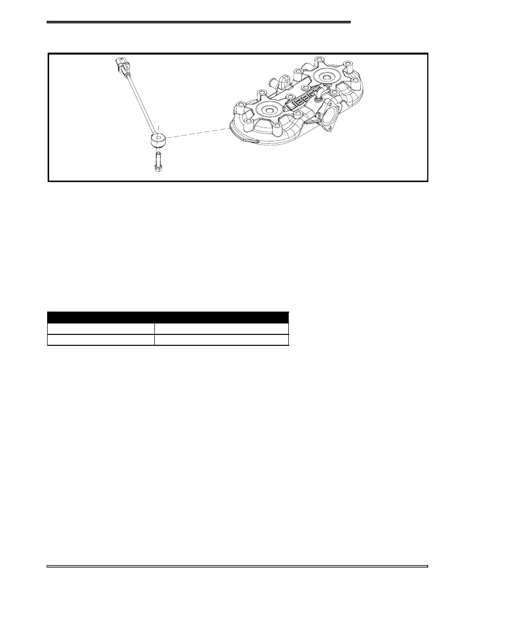
900 LIBERTYT DETONATION SENSOR (DET)
A detonation sensor monitors the engine and responds to detonation by automatically reducing the engine timing and adding fuel.
The activated sensor reduces engine detonation by compensation of timing and fuel. This results in decreased engine RPM and
performance.
This sensor detects engine knock by converting pressure pulses from the engine and converting the pulses to a voltage. The ECU
has a threshold voltage to differentiate between normal and damaging detonation. This system operates similar to existing DET
system, but this system can compensate with timing and fuel delivery.
DET TROUBLESHOOTING
Use this chart to determine causes and solutions for detonation. If none of these conditions exists and the sensor remains activated
you may need to remove the sensor from the engine and test run the unit, and if the conditions are gone you will need to check
the possible causes again. If the conditions remain the same you may need to replace the sensor.
Possible Cause
Solution
Poor quality fuel
Replace with higher quality fuel
Improper engine modifications
Do not modify the engine
EFFECT OF DET
Basic concept of the detonation system is to avoid damage to the engine from detonation while developing the maximum power
of the engine safely.
The system starts with a predetermined engine perimeters.
If the system senses detonation that is beyond a preset limit, the system retards the ignition timing to reduce the detonation and
prevent engine damage.
When the detonation returns to a permissible level, the system will incrementally advance the spark to increase the output of the
engine in a safe manner.
SENSOR FAIL SAFE
The Detonation Elimination Technology also includes a sensor fail--safe system to prevent the engine from damage, when the
sensor has failed, been disconnected or is unable to detect detonation. DET failure will add 10% injector duration and the ECU
will use other sensors.
The rider will experience a loss in power. The sensor will need to be reconnected or repaired to once again achieve full power.
Check engine light will flash 6 times if the sensor fails or becomes disconnected.
The ECU will default the DET value to a set percentage and will monitor other sensors for reduced performance.