Snowmobile Polaris DEEP SNOW (2005 year). Manual - part 66


  Index      Snowmobiles / ATV     Snowmobile Polaris DEEP SNOW (TRAIL RMK, 600 RMK, 700 RMK, 800 RMK, 900 RMK, 600 SWITCHBACK, 800 SWITCHBACK) - service manual 2005 year


Search            


Content   ..  64  65  66  67   ..


Snowmobile Polaris DEEP SNOW (2005 year). Manual - part 66


ELECTRICAL

13.21

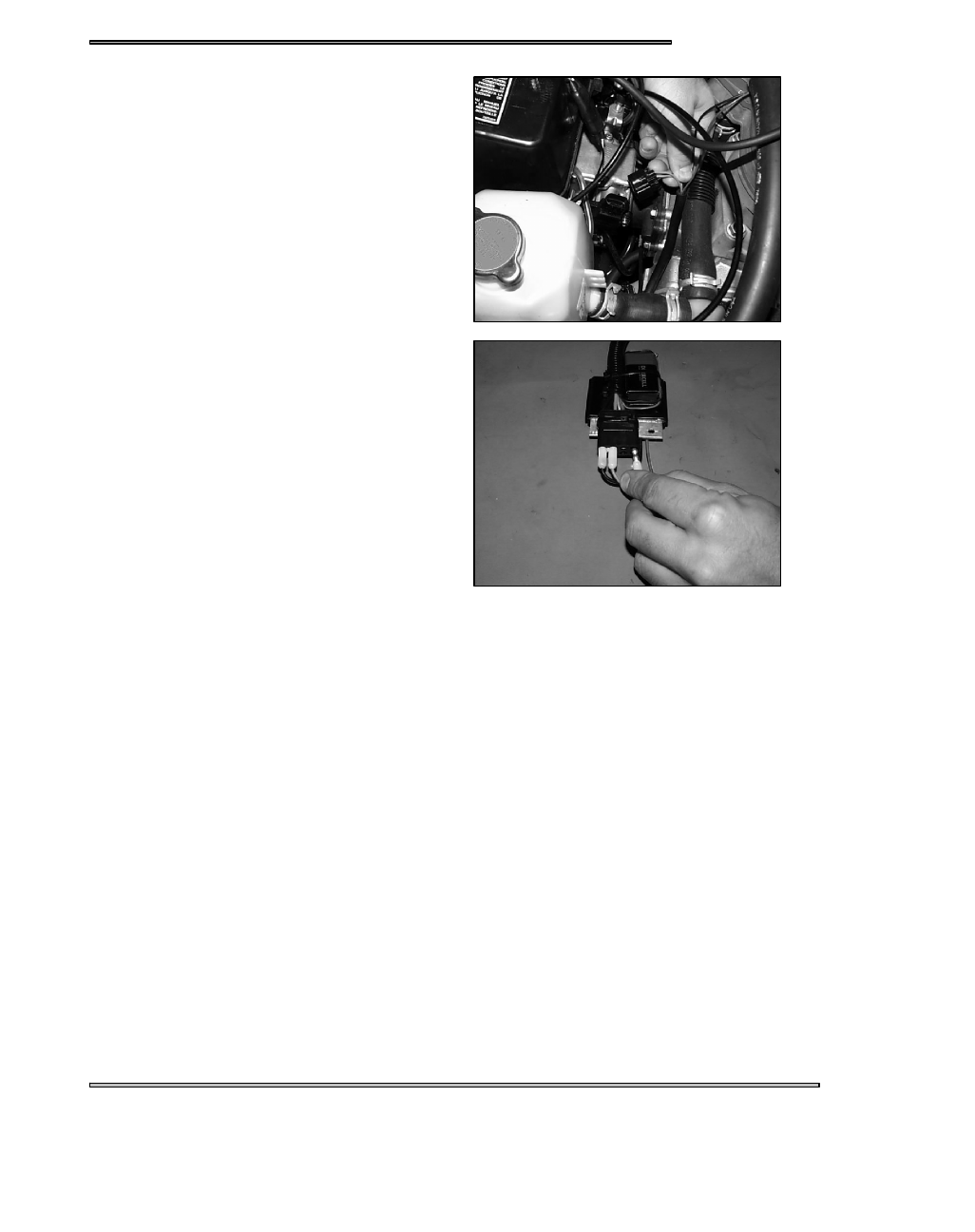
4. When the TPS is set and voltage is verified, remove the

tester and re-install the snowmobile TPS harness.

5. When storing the TPS tester, remove the red terminal of

the tester and insert it in the blank terminal of the harness.

ELECTRICAL

13.22

900 THROTTLE BODY

A

B

C

D

E

F

ELECTRICAL

13.23

TPS SETTING PROCEDURE

The TPS comes set from the factory and should not need any adjustments. If replacing a TPS or resetting the TPS, Polaris has
developed a TPS test kit for aid in setting the Throttle Position Sensor to specification.
1. Assemble your TPS sensor tool (PN 2201519) as per the instructions that came with the tool.
2. Make sure your 9 volt battery is in good condition by inserting the black volt meter probe from your Fluket meter in the black

terminal and the red probe into the pink terminal. Voltage should read 4.99 to 5.01 volts. If not, try a new 9 volt battery.

3. Insert the red voltmeter lead into the yellow terminal, and black lead to the black terminal. Slowly open throttle and check for

smooth voltage change.

NOTE:

The Fluke meter will change scales and show O.L. momentarily when throttle is opening.

4. Turn the idle set screw (A) counter clockwise until the screw tip (B) separates from the adjusted lever tab.
5. Turn the synchronization screw (C) counter clockwise until the synchronization lever is touching the synchronization screw

hole (D) tab.

6. Remove the connector from the TPS on the throttle body and install TPS sensor tool on to the TPS.
7. Place a shop towel under the throttle body incase you loose grip on the spring.
8. Remove the synchronization lever tab spring (E) and gently open and then close the throttle plates with the throttle, allowing

the plate to close gently. Note the voltage at this point.

9. Insert the synchronization lever tab spring and screw.
10. Turn the synchronization screw clockwise until the volt meter reads the voltage level that you noted in step #8.
11. Loosen screws on the TPS sensor (F).
12. Adjust the TPS sensor until the voltage on the volt meter reads .705 -- .715 volts.
13. Tighten the TPS retaining screws, making sure that the voltage continues to read .705 -- .715 volts.
14. Turn the idle set screw clockwise until the voltage reads .930 volts.
15. Voltage at the yellow terminal should be .93 volts +.02v at idle. Once the TPS voltage is verified and set, remove the sensor

tool and re--install the TPS harness.

IQ FUSION/RMK THROTTLE POSITION SENSOR (TPS)

0.93 volts (±.02v) @ Idle

R/W

(from ECU)

Lite Blue

BLK/BL

NOTE:

The 900 Libertyt engine TPS is set at .93volts ±.02v at idle.

When the sensor is inoperative or disconnected the system will switch to a “LIMP HOME” mode. Limp Home mode reduces
performance to a default value and monitors other sensors.

ELECTRICAL

13.24

900 LIBERTY TEMPERATURE LIGHT

A

B

The TEMP light (A) is controlled by the CDI using water temperature input from the water temp sensor (B), throttle position input

(TPS) and RPM input. The water temp sensor is a thermistor. As the temperature increases the resistance decreases. Each input

has thresholds programmed into the CDI for when to illuminate the TEMP light according to coolant temp, throttle position (TPS)

and engine speed (RPM).

For example, the TEMP light will come on at idle (under 2000 RPM, 0% throttle) and coolant temperature of 230_F (110_C).

Timing retard initiates at 176_F and a TPS of over 80--100%. For more severe conditions, the engine fail--safe is turned on at high

TPS input and high temps.

TEMP _F (_C)

Ω RESISTANCE RANGE

68 (20)

2189 -- 2675

149 (65)

455 -- 556

203 (95)

197 -- 240

239 (115)

120 -- 147

275 (135)

77 -- 94

LAMP CIRCUIT TEST

1. Ground the Black/White wire from the Temperature light.
2. Run the machine, and light should be on.

THERMISTOR SENSOR TEST

At room temperature 68_ F (20_ C) the Thermistor should read 2190 to 2575 Ω. See chart above for other temperature resistances.

CAUTION:

If attempting to heat the sensor, heat only in a water bath. Never subject the sensor to an open flame to attempt to close the contacts

as sensor damage may result.


Content   ..  64  65  66  67   ..