Snowmobile Polaris DEEP SNOW (2005 year). Manual - part 61
 

  Index      Snowmobiles / ATV     Snowmobile Polaris DEEP SNOW (TRAIL RMK, 600 RMK, 700 RMK, 800 RMK, 900 RMK, 600 SWITCHBACK, 800 SWITCHBACK) - service manual 2005 year


Search            


Content   ..  59  60  61  62   ..


Snowmobile Polaris DEEP SNOW (2005 year). Manual - part 61


ELECTRICAL

13.1

Typical Multimeter Usage

Multimeter Usage

The easiest and most accurate method for testing modern electri-

cal components is with a digital multitester. Any good quality multi-

tester will work. However, due to ease of operation and durability,

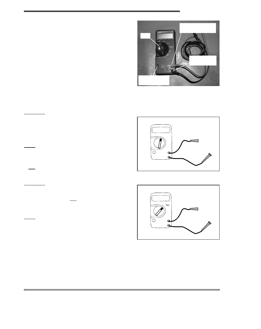
Polaris recommends the Fluke Model 73 (PN 2870659), or Tektro-

nix DMM155. See photo at right. This instrument will provide a dig-

ital readout of the measured value of the test being performed.
Listed below are the dial symbols, their meaning and what the dial

setting can be used for.
Off = Instrument Off

V= Volts AC - measuring alternator output
Used to measure AC voltage in an electrical system. AC voltage

is produced from every coil on the stator plate when a magnet is

passed by it.
Test Method
1. Connect black lead to Com (--) meter terminal.
2. Connect red lead to V

(+) meter terminal.

3. Turn selector dial to V

~

setting.

4. Connect test leads parallel with test component. The polarity of

the leads is not important.

Usage

S

Test unregulated voltage output of a stator coil

S

Test regulated voltage to the lights and handwarmers

- - - = Volts DC - measuring battery voltage, volt drop, etc.
Used to measure DC voltage produced by a battery or rectifier.
Test Method
1. Connect black lead to Com (--) meter terminal
2. Connect red lead to V

(+) meter terminal.

3. Turn selector dial to V - - - setting.
4. Connect test leads parallel with test component. Observe

polarity.

Usage

S

Test battery voltage

S

Test DC regulator

S

Test voltage drop for bad connections

S

Test supply voltage to electric fuel gauge

Dial

Red Lead here
for Volts and Ohms

Common
(Black Lead)

Red Lead here
for Amperes

+

_

17.29

V

~

VAC

+

_

12.95

V

VDC

ELECTRICAL

13.2

Ω = Ohms, resistance - measuring component resistance values - testing coils, wiring, etc.
Used to test resistance to the flow of electricity in a circuit or compo-

nent. A reading of OL means an open circuit or infinite resistance.

Sometimes the leads themselves will have some resistance. Touch

the leads together and subtract this resistance from the component

reading to achieve the actual reading.
Test Method
1. Connect black lead to Com (--) meter terminal
2. Connect red lead to V

(+) meter terminal.

3. Turn selector dial to Ω setting.
4. Isolate test component from the rest of the electrical circuit by

disconnecting wires from harness.

5. Connect test leads to the circuit to be tested.
Usage

S

Testing coil resistance

S

Testing switch operation

S

Testing wire continuity

A~= Amps AC - used to test lighting coil output
Used to test the power of an alternator coil.
Test Method
1. Connect black lead to Com (--) meter terminal
2. Connect red lead to 10A (+) meter terminal.
3. Disconnect engine harness from system.
4. Connect across the specified coil wires.
5. Start engine and let it idle.
6. Readings should be above 5 Amps at any RPM. NOTE: It is

not necessary to increase RPM. The reading can be obtained

at idle.

Usage

S

Testing stator coil power output.

- - - = Amps DC - used to check battery charge rate, system draws, etc.
Used to check the current flow to and from the battery.
Test Method
1. Make sure red lead is in the 10A terminal of the meter and the black lead is in the Com (--) terminal of the meter.
2. Disconnect battery ground wire(s) from battery (--) terminal.
3. Connect red meter lead to battery (--) terminal.
4. Connect black meter lead to harness ground wires and cable.

CAUTION:

Do not operate electric starter (if equipped) or meter damage may occur.NOTE: When using the DC Amp settings, the

red test lead must be moved to the 10A socket on the front of the instrument.
Usage

S

Testing key off current draw and Testing charging system break even RPM

S

Testing key on current draw and Testing DC current flow (direction), is battery charging?

+

_

00.2 Ω

+

_

14.00

A~

AC

ELECTRICAL

13.3

IGNITION TIMING

0

5

10

15

20

25

30

1000

2000

3000

4000

RPM

TIMING

DE-

GREES

EXAMPLE: 10@ 2500 RPM

NOTE:

Always verify timing of engine at room temperature (68_ F / 20_ C) only, and at the proper RPM.
If applicable make sure the key switch is in the PREMIUM mode and the TPS is unplugged.

To obtain the best ignition timing accuracy and reduce the chance of error, the ignition timing specification is given at a “flat”

portion of the advance curve. This flat portion on the curve is where the base ignition timing is specified. Refer to the specification

chapter for model specific timing specification. Ignition timing must be checked at the specified RPM, or an inaccurate timing

will result.

If engine damage has occurred due to a suspected ignition related problem, verify the ignition timing is correct at the specified

operating RPM.

TIMING PROCEDURE

Refer to the model timing specifications for correct timing.
Remove the MAG side spark plug.
Install the dial indicator into the spark plug hole. You may need to use a different adaptor depending the size of the spark plug

hole.
Find out the measurement for degrees that is specified for the model that you are checking by taking you base timing degree and

cross referencing it to the appropriate engine listed on the chart on page 13.4 and write it down.
Rotate the crankshaft by hand while observing the dial indicator. As the piston touches the indicator plunger, the dial will begin

to rotate. Find the point where the pointer stops rotating and reverses direction. This will be Top Dead Center (TDC).
While holding the crankshaft with the piston at TDC, zero the dial indicator by rotating the bezel until the “0” until it is aligned

with the pointer.
Rotate the crankshaft in the opposite direction of rotation .250” Before Top Dead Center (BTDC). This will be 2 1/2 pointer revo-

lutions.
At this point you will rotate the crankshaft the specified measurement that you wrote down earlier.
While holding the crankshaft at this correct timing position, mark the flywheel with a white marker or white paint directly in--line

with the stationary pointer in the timing window on the recoil side.
Once the flywheel is marked, remove the dial indicator and replace the spark plug and cap.
Connect a good quality timing light to the engine (follow the timing light manufactures instructions).
Disconnect the TPS if applicable.

Place sled on track stand and start the engine and increase engine RPM to the point specified in the timing specification. Hold

the throttle to maintain specified timing RPM.

ELECTRICAL

13.4

If the ignition timing specification is listed in degrees only, convert to either inches or mm BTDC and use a dial indicator to

verify timing marks. Disconnect the TPS (Throttle Position Sensor) connector from carburetors on models with TPS.

NOTE: Due to differing rod lengths and engine strokes, consult the engine model list for correct engine.


Content   ..  59  60  61  62   ..