Snowmobile Polaris DEEP SNOW (2005 year). Manual - part 62


  Index      Snowmobiles / ATV     Snowmobile Polaris DEEP SNOW (TRAIL RMK, 600 RMK, 700 RMK, 800 RMK, 900 RMK, 600 SWITCHBACK, 800 SWITCHBACK) - service manual 2005 year


Search            


Content   ..  60  61  62  63   ..


Snowmobile Polaris DEEP SNOW (2005 year). Manual - part 62


ELECTRICAL

13.5

Timing Procedure - All Models

NOTE: Always check ignition timing with the engine at room temperature only (20_C/68_F), and with the key switch in

the PREMIUM mode (if applicable).
1. Refer to the timing specification charts at the beginning of this section to determine the proper ignition timing for the

engine you are working on.

2. Use a dial indicator to place the piston in the proper timing position and mark the flywheel at this point (follow

procedure outlined in this chapter).

3. Connect an accurate tachometer and a good quality timing light to the engine according to manufacturer’s

instructions. Disconnect the TPS (Throttle Position Sensor) connector from carburetors on models with TPS.

4. Start engine and increase RPM to the point specified in

the timing specifications in Chapter 1. Hold the throttle

to maintain specified timing RPM.

5. Point the timing light at the timing inspection hole.
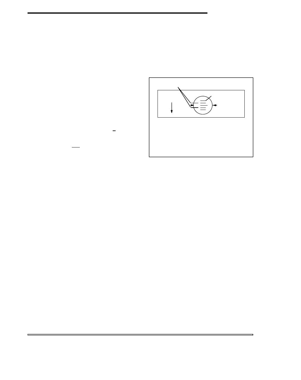
6. With your head positioned so there is a straight line

between your eye, the stationary pointer and the

crankshaft center line, note the relative position

between the marked flywheel line and the stationary

pointer. If the stationary pointer is aligned with the mark

made in Step 2, (or within the acceptable + variance) the

timing is correct.

7. If the pointer is outside the variance, the stator will have

to be rotated either with crankshaft rotation (to retard the

timing) or against rotation to advance it.

NOTE:

Rotate stator plate approximately the same distance as the marks must move.

NOTE:

In most cases, the recoil starter housing, recoil drive hub, and flywheel must be removed to loosen the stator

bolts and change the timing. On some engines, the stator plate retaining screws can be accessed through the flywheel.
8. Torque stator plate screws and flywheel nut to specified torque. Apply Loctite 262 (red) to crankshaft flywheel taper

if required. Refer to the Specifications section for torque specifications and flywheel installation procedure for

engine type.

Preparing a New Battery for Service

To ensure maximum service life and performance from a battery, it must have proper initial servicing. To service a new

battery, the following steps must be taken. NOTE: Do not service the battery unless it will be put into regular service

within 30 days.

1. Remove vent plug from vent fitting.

2. Fill battery with electrolyte to the upper level marks on the case.

3. Set battery aside and allow it to cool and stabilize for 30 minutes.

4. Add electrolyte to bring the level back to the upper level mark on the case. NOTE: This is the last time that

electrolyte should be added. If the level becomes low after this point, add only distilled water.

5. Charge battery at 1/10 of its amp/hour rating.

Example:1/10 of 9 amp battery = .9 amps, 1/10 of 14 amp battery = 1.4 amps, 1/10 of 18 amp battery = 1.8 amps

(recommended charging rates).

6. Check specific gravity of each cell with a hydrometer to ensure each has a reading of 1.270 or higher.

Flywheel

Rotation

Acceptable Variance

Flywheel Lines

Stationary

Pointers

NOTE: Acceptable variance is usually

one line on either side of the dial indicated

timing mark.

Liquid Cooled

ELECTRICAL

13.6

Battery Testing

There are three easy tests which can determine battery condition. Whenever the complaint is related to either the start-

ing or charging systems, the battery should be checked first.
Lead-acid batteries should be kept at or as near full charge as possible. If the battery is stored or used in a partially

charged condition, hard crystal sulfation will form on the plates, reducing their efficiency and possibly ruining the battery.

Open Circuit Voltage Test (OCV)

Battery voltage should be checked with a digital multitester. Readings of 12.6 or less require further battery testing and

charging.

Specific Gravity Test

A tool such as the battery hydrometer (PN 2870836) can be used to measure electrolyte strength or specific gravity.

As the battery goes through the charge/discharge cycle, the electrolyte goes from a heavy , more acidic state at full

charge to a light, more water state when discharged. The hydrometer can measure state of charge and differences

between cells in a multi-cell battery. Readings of 1.270 or greater should be observed in a fully charged battery. Differ-

ences of more than .025 between the lowest and highest cell readings indicate a need to replace the battery.

State Of Charge

Conventional

Lead-acid

Yumacron

Type

100% Charged

12.60V

12.70V

75% Charged

12.40V

12.50V

50% Charged

12.10V

12.20V

25% Charged

11.90V

12.0V

0% Charged

Less Than

11.80V

Less Than

11.9V

State Of Charge*

Conventional

Lead-acid

Yumacron

Type

100% Charged

1.265

1.275

75% Charged

1.210

1.225

50% Charged

1.160

1.175

25% Charged

1.120

1.135

0% Charged

Less Than

1.100

Less Than

1.115

*at 80° F

NOTE: Subtract .01 from the specific gravity for electrolyte at 40° F and compare these values to the chart.

Detail A

ELECTRICAL

13.7

Load Test

NOTE:

This test can only be performed on machines equipped with electric start. This test cannot be performed if the

engine or starting system is not working properly.
A battery may indicate a fully charge condition on the OCV test and the specific gravity test, but still not have the storage

capacity necessary to properly function in the electrical system. For this reason, a battery capacity or load test should

be conducted whenever poor battery performance is encountered.
To perform the test, hook a multitester to the battery in the same manner as in the OCV test. The reading should be

12.6 volts or greater. Engage the electric starter and view the registered battery voltage while cranking the engine.

Continue the test for 15 seconds. During this cranking period, the observed voltage should not drop below 9.5 volts.

If the beginning voltage is 12.6 or higher and the cranking voltage drops below 9.5 volts during the test, replace the

battery.

Refilling a Low Battery

The normal charge/discharge cycle of a battery causes the cells to give off gases. These gases, hydrogen and oxygen,

are the components of water. Because of the loss of these gases and the lowering of the electrolyte level, it will be

necessary to add pure, clean distilled water to bring the fluid to the proper level. After filling, charge the battery to raise

the specific gravity to1.270 or greater.

Off Season Storage

To prevent battery damage during extended periods of non-use, the following basic maintenance items must be per-

formed.
1. Remove battery from machine and wash the case and battery tray with a mild solution of baking soda and water.

Rinse with lots of fresh water after cleaning. CAUTION: Do not allow any of the baking soda solution to enter the

battery or the acid will be neutralized.

2. Using a wire brush or knife, remove any corrosion from the cables and terminals.
3. Make sure the electrolyte is at the proper level. Add distilled water if necessary.
4. Charge at a rate no greater than 1/10 of the battery’s amp/hr capacity until the electrolyte’s specific gravity reaches

1.270 or greater.

5. The battery may be stored either in the machine with the cables disconnected, or on a piece of wood in a cool place.

NOTE: Stored batteries lose their charge at the rate of 1% per day. They should be fully recharged every 30 to 60

days during a non-use period. If stored during winter months, the electrolyte will freeze at higher temperatures as

the battery discharges. The chart indicates freezing points by specific gravity.

Specific Gravity of Electrolyte

Freezing Point

1.265

-75° F

1.225

-35° F

1.200

-17° F

1.150

+5° F

1.100

+18° F

1.050

+27° F

Charging Procedure

Charge battery with a charger no larger than 1/10 of the bat-

tery’s amp/hr rating for as many hours as needed to raise the

specific gravity to 1.270 or greater.

WARNING

The gases given off by a battery are explosive. Any spark

or open flame near a battery can cause an explosion which

will spray battery acid on anyone close to it. If battery acid

gets on anyone, wash the affected area with large quantities

of cool water and seek immediate medical attention.

Battery electrolyte is poisonous. It contains acid!
Serious burns can result from contact with the skin,

eyes, or clothing.
ANTIDOTE:
EXTERNAL: Flush with water.
INTERNAL: Drink large quantities of water or milk.

Follow with milk of magnesia, beaten egg, or vegeta-

ble oil. Call physician immediately.
EYES: Flush with water for 15 minutes and get prompt

medical attention.
Batteries produce explosive gases. Keep sparks,

flame, cigarettes, etc. away. Ventilate when charging

or using in closed space. Always shield eyes when

working near batteries.
KEEP OUT OF REACH OF CHILDREN.

WARNING

ELECTRICAL

13.8

Dynamic Testing of the Electric Starting System

Condition: Starter fails to turn motor or motor turns slowly.
NOTE: Be sure the engine crankshaft is free to turn before proceeding. For this test a digital multitester must be used.

Meter connections are shown later in this chapter.

With tester on VDC, place tester black lead on battery

negative (-) terminal and tester red lead on battery posi-

tive (+) terminal. (A) Page 13.9. Reading should be

12.6V or greater. Is it?

No

!

Yes

#

Remove battery, test and/or service. Install a fully

charged shop battery to continue the test.

(Continue with left column)

Disconnect red engagement coil wire from start sole-

noid. Connect black tester wire to an appropriate

ground and red lead to red harness wire at solenoid.

(F) page 9.13. Rotate ignition key to the start position.

Meter should read battery voltage. Does it?

No

!

Yes

#

With black tester lead on ground, check for voltage at

large relay in terminal,, circuit breaker in and out termi-

nals, and across both sides (red and red/white) of the

ignition switch with switch on start. Repair or replace

any defective parts.

Reconnect solenoid, connect tester black lead to bat-

tery positive terminal and red tester lead to solenoid

end of battery to solenoid cable. (B) Page 13.9. Turn

key to start position. The reading must be less than .1V

DC. Is it?

No

!

Yes

#

Clean battery to solenoid cable ends or replace cable.

Connect black tester lead to solenoid end of battery to

solenoid cable and red tester lead to solenoid end of

solenoid to starter cable. (C) Page 13.9. Turn key to

start position. The reading must be less than .1V DC.

Is it?

No

!

Yes

#

Replace starter solenoid.

Connect black tester lead to solenoid end of solenoid to

starter cable and red tester lead to starter end of same

cable. (D) Page 13.9. Turn key to start position. The

reading must be less than .1V DC. Is it?

No

!

Yes

#

Clean solenoid to starter cable ends or replace cable.

Connect black tester lead to starter frame. Connect red

tester lead to battery negative (-) terminal. (E) Page

13.9. Turn key to start position. The reading should

be less than .1V DC. Is it?

No

!

Yes

#

Clean ends of engine to battery negative cable or re-

place cable.

If all these tests indicate a good condition, yet the starter still fails to turn, or turns slowly, the starter must be re-

move for static testing and inspection.


Content   ..  60  61  62  63   ..