Snowmobile Polaris DEEP SNOW (2005 year). Manual - part 47


  Index      Snowmobiles / ATV     Snowmobile Polaris DEEP SNOW (TRAIL RMK, 600 RMK, 700 RMK, 800 RMK, 900 RMK, 600 SWITCHBACK, 800 SWITCHBACK) - service manual 2005 year


Search            


Content   ..  45  46  47  48   ..


Snowmobile Polaris DEEP SNOW (2005 year). Manual - part 47


STEERING

9.11

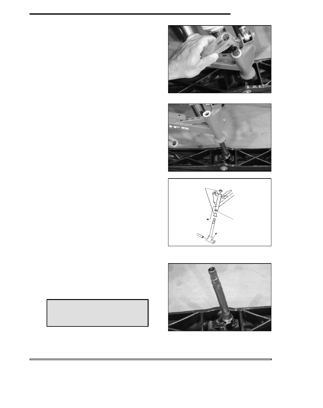
SKI SPINDLE BUSHING REMOVAL

1. Remove steering arm.

2. Slide spindle and ski assembly out bottom of trailing arm and

Inspect spindle for wear or damage.

3. Remove old bushings and washer from bottom of spindle tube

with a drift punch. Inspect condition of washer and replace if

worn. Install new bushings, tapered end first.

SKI SPINDLE BUSHING INSTALLATION

4. Grease spindle shaft and new bushings with Polaris All Season

Grease.

Washer

Bushings

All Season Grease

PN 2871322 (3 oz.)

PN 2871423 (14 oz.)

STEERING

9.12

5. Install spindle into trailing arm with grease fitting facing

rearward.

6. With ski facing straight forward, attach steering arm.

7. Install steering arm bolt and torque to specification.

STEERING ARM ORIENTATION

WARNING

Steering arm orientation is important to ensure proper steering tie rod end thread engagement and steering performance.

Always mark steering arms and spindles before removal for reference upon reassembly. When installing new parts or after

steering arm installation, refer to the illustrations and text below. Always verify proper steering operation after complet-

ing adjustments or repairs.

1. The steering arms on each spindle should be parallel to slightly

inward in relation to each ski. When correctly installed the

centerline of the ski and centerline of the ski bolt hole in the

spindle will form (approximately) a 90_ angle or slightly greater.

2. If the steering arm is installed incorrectly the threads of the

steering tie rod end will not engage the tie rod sufficiently, and the

angle formed between ski and ski bolt centerlines is considerably

less than 90° as shown at right.

3. Reinstall torsion bar linkage (where applicable). Torque attaching

bolts to specification.

Spindle Bolt Torque

28-30 ft. lbs. (38.6-41.4 Nm)

Forward

Steering Arm

Bolt Torque

30 ft. lbs.

(41.5 Nm)

As Close To

90° As Possible

Threads engage

tie rod at least

3/4″ (19mm).

≥90°

Correct

STEERING

9.13

SKI INSTALLATION

SKI INSTALLATION - COMPOSITE

-

Install ski stop with large

portion toward rear of ski.*

*Optional position. Normal instal-
lation consists of large end for-
ward.

-

Install cotter pin

and bend both legs.

-

Install ski to spindle. From outside of ski, install bolt,

washers, and castle nut. Torque to 36 ft.lbs. (5 Nm)

-

Carefully lower machine.

-

Install ski over spindle, slight-

ly in front of ski saddle with ski

pointing outside.

SKI INSTALLATION - STEEL SKIS

-

Slide ski forward until spindle

is just behind ski saddle and turn

to the forward position.

-

Slide ski forward so spindle is

behind ski saddle.

-

Apply soapy water solution to

the rear portion of the rubber ski

stop. Install ski stop on top of ski

saddle with large portion forward.

-

Push ski back to slide spindle

into place. From outside of ski,

install bolt and castle nut. Torque

to 36 ft. lbs. Install cotter pin and

bend both legs

Forward

Rubber

Ski

Stop

Front

of ski

Ski Spindle

Ski Saddle

STEERING

9.14

SKI INSTALLATION

EDGE TORSION BAR REMOVAL

1. Remove trailing arm assembly if applicable.

2. Using a small pin punch, tap out the rivet mandrels in the center of

the torsion bar support rivets.

3. Using a 1/4“ bit, drill out the center portion of the rivets.

4. Punch out the rivet body.

5. Remove support and torsion bar.

6. Repeat procedure for second torsion bar.

EDGE TORSION BAR INSTALLATION

1. Rivet support in place using Polaris PN 7621449 rivets.
These high strength “Q” rivets are the only replacement rivets recom-
mended for this application.

2. Reinstall torsion bar.

3. Reinstall trailing arm assembly.

4. Check camber and toe adjustments.

ACCUTRAC SKI INSTALLATION

-

Install Ski to spindle. From outside

of ski, install bolt, washers and nylok

nut. Torque to 36 ft. lbs. (4.97 kg-m).

-

Carefully lower machine

-

Install ski stop with tall portion

toward front of saddle-less ski.

NOTE: These washers are

slightly concave. The inside

curve should go toward the ski.

Ski

Washer

-

Saddle-less skis will not require

the use of the metal support.

-

When installing a saddle-less ski

with this type of ski stop, the 90_ flat por-

tion of stop should face toward the front

of the ski.

Torsion Bar Support Rivets

PN 7621449


Content   ..  45  46  47  48   ..