Snowmobile Polaris DEEP SNOW (2005 year). Manual - part 35
CLUTCHING
6.8
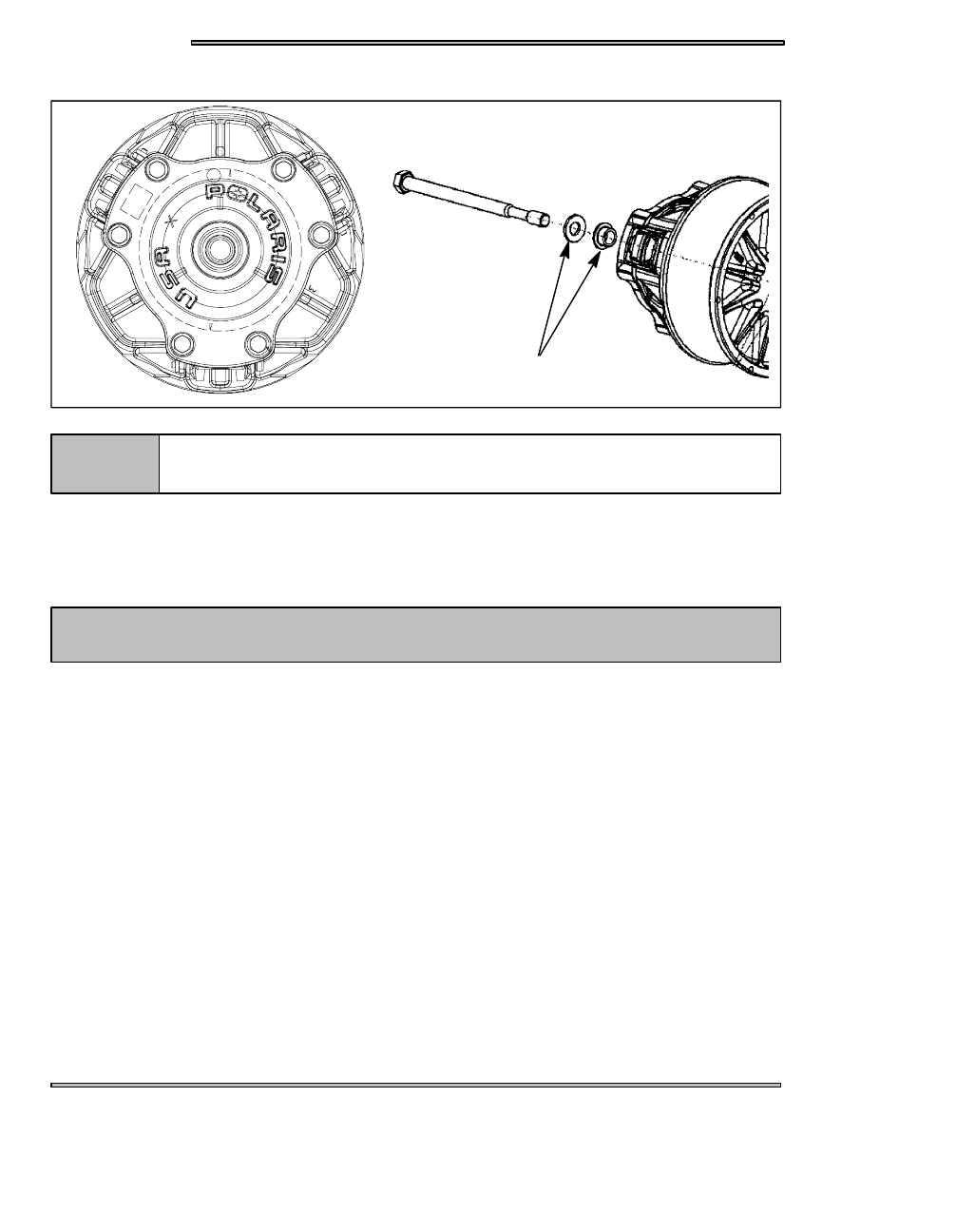
DRIVE CLUTCH REMOVAL
(A)
(B)
NOTE:
Keep track of the washers on the clutch retaining bolt.
Clutch puller part numbers can be found on page 6.1.
DRIVE CLUTCH REMOVAL
1. Remove the belt, see page 3.13.
2. With clutch holding tool (PN 931477--A) in place remove the clutch retaining bolt. Note the location and the orientation of the
washers (B) are placed on the clutch bolt.
3. Insert the correct clutch puller and tighten puller into clutch.
DO NOT USE AN IMPACT WRENCH OR DAMAGE TO THE CLUTCH OR CRANKSHAFT
MAY OCCUR.
CAUTION
4. Strike the clutch puller with a dead blow hammer, if the clutch does not come off, tighten up the clutch puller some more and
strike it again, repeat until the clutch “pops” off.