Snowmobile Polaris DEEP SNOW (2005 year). Manual - part 21
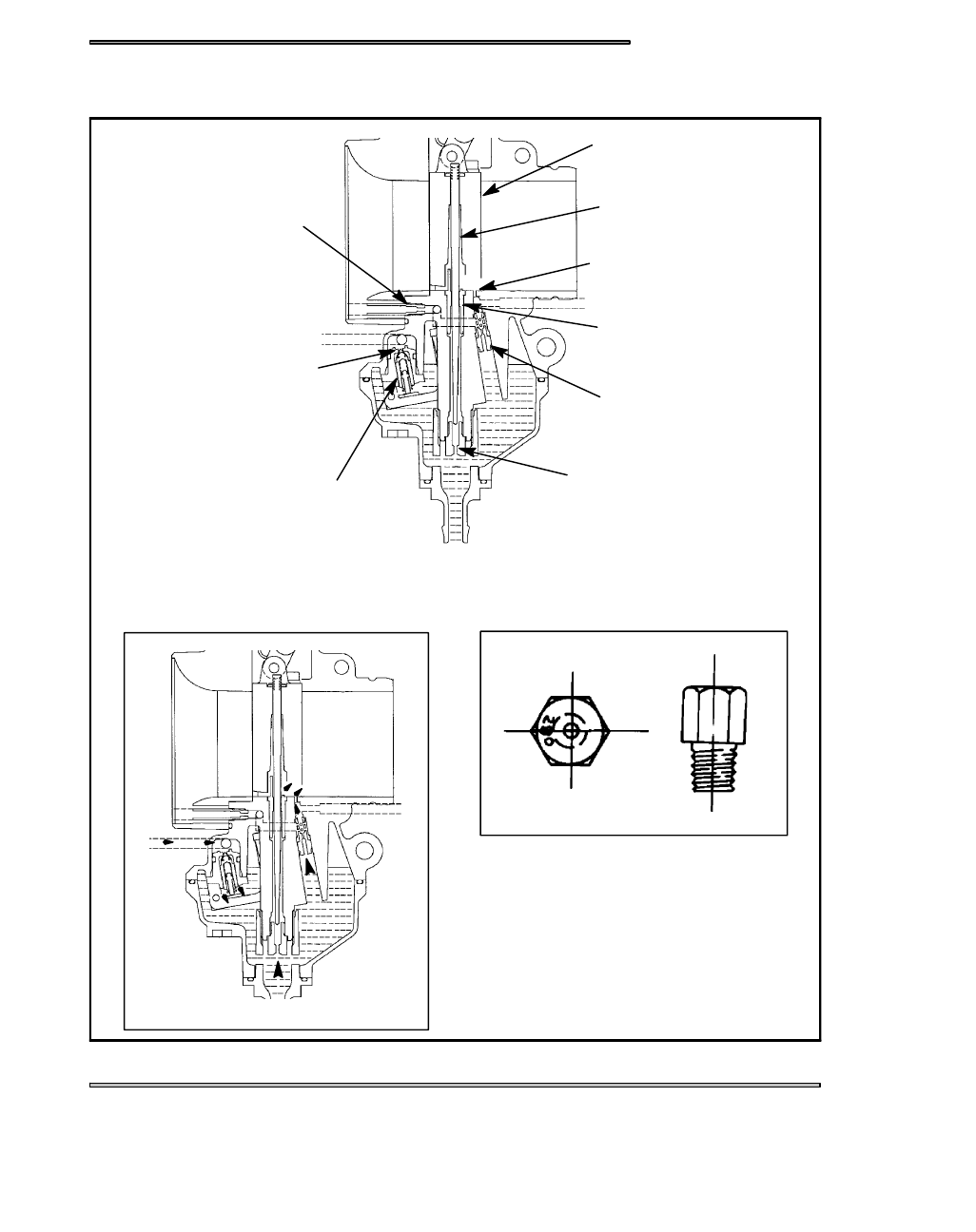
FUEL DELIVERY
4.9
MIKUNI CARBURETOR
THROTTLE VALVE
JET NEEDLE
BY--PASS HOLE
NEEDLE JET
PILOT JET
MAIN JET
VALVE SEAT
NEEDLE VALVE
PILOT AIR JET
MAIN JET
FUEL DELIVERY
Index Snowmobiles / ATV Snowmobile Polaris DEEP SNOW (TRAIL RMK, 600 RMK, 700 RMK, 800 RMK, 900 RMK, 600 SWITCHBACK, 800 SWITCHBACK) - service manual 2005 year
|
|
|
FUEL DELIVERY 4.9 MIKUNI CARBURETOR THROTTLE VALVE JET NEEDLE BY--PASS HOLE NEEDLE JET PILOT JET MAIN JET VALVE SEAT NEEDLE VALVE PILOT AIR JET MAIN JET FUEL DELIVERY |