Snowmobile Polaris DEEP SNOW (2005 year). Manual - part 19


  Index      Snowmobiles / ATV     Snowmobile Polaris DEEP SNOW (TRAIL RMK, 600 RMK, 700 RMK, 800 RMK, 900 RMK, 600 SWITCHBACK, 800 SWITCHBACK) - service manual 2005 year


Search            


Content   ..  17  18  19  20   ..


Snowmobile Polaris DEEP SNOW (2005 year). Manual - part 19


FUEL DELIVERY

4.1

Whenever servicing the carburetor or fuel system, it is important to heed the following warnings.

WARNING

Gasoline is extremely flammable and explosive under certain conditions.

Always stop the engine and refuel outdoors or in a well ventilated area.

Do not smoke or allow open flames or sparks in or near the area where refueling is performed or where gasoline is stored

or used.

Do not overfill the tank. Do not fill the tank neck.

If you get gasoline in your eyes or if you swallow gasoline, see your doctor immediately.

If you spill gasoline on your skin or clothing, immediately wash it off with soap and water and change clothing.

Never start the engine or let it run in an enclosed area. Gasoline powered engine exhaust fumes are poisonous and can

cause loss of consciousness and death in a short time.

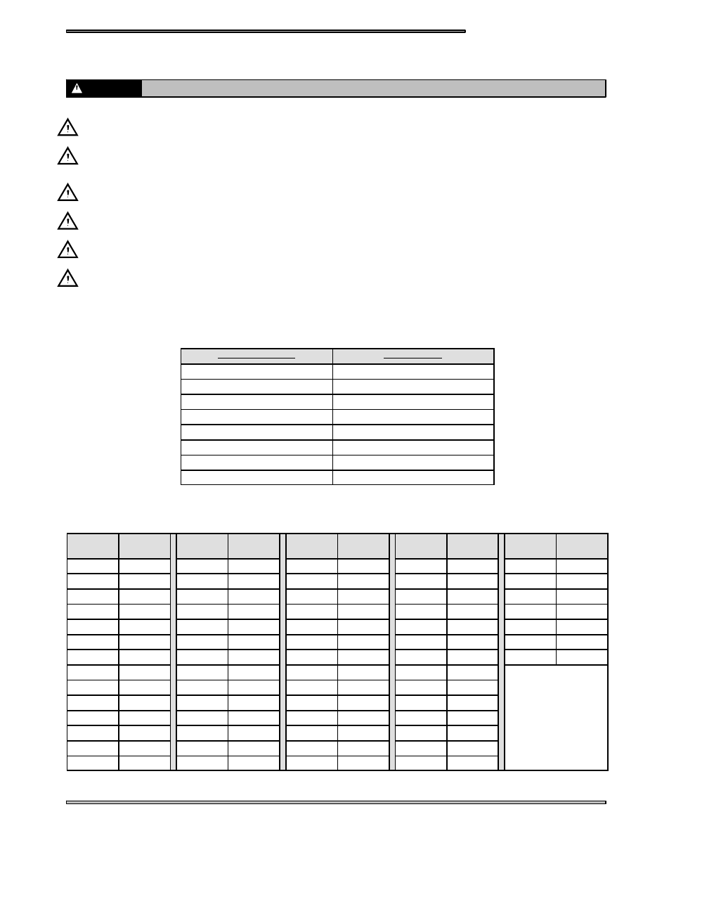
MIKUNI JET PART NUMBERS

The following chart lists main and pilot jets and the part number of each that are presently available.

PILOT JET NUMBER

PART NUMBER

25

3130064

30

3130065

35

3130066

40

3130067

45

3130068

50

3130629

55

3130070

60

3130071

MIKUNI HEX HEAD MAIN JET PART NUMBERS

MAIN JET

NUMBER

PART

NUMBER

MAIN JET

NUMBER

PART

NUMBER

MAIN JET

NUMBER

PART

NUMBER

MAIN JET

NUMBER

PART

NUMBER

MAIN JET

NUMBER

PART

NUMBER

80

3130099

150

3130113

240

3130127

380

3130140

530 N

3131402

85

3130100

155

3130114

250

3130128

390

3130480

540 N

3131408

90

3130101

160

3130115

260

3130129

400

3130141

550 N

1311409

95

3130102

165

3130116

270

3130130

410

3130599

560

3130151

100

3130103

170

3130117

280

3130131

420

3130142

560 N

3131410

105

3130104

175

3130118

290

3130132

430

3130143

590

3130152

110

3130105

180

3130119

300

3130133

450

3130144

620

3130153

115

3130106

185

3130120

310

3130134

460

3130146

120

3130107

190

3130121

320

3130135

470

3130147

125

3130108

195

3130122

330

3130136

490

3130148

130

3130109

200

3130123

340

3130137

500

3130149

135

1310110

210

3130124

350

3130138

510 N

3131400

140

3130111

220

3130125

360

3130139

520 N

3131401

145

3130112

230

3130126

370

3130290

530

3130150

FUEL DELIVERY

4.2

MIKUNI TM JET PART NUMBERS

JET NEEDLES

PART NUMBER

PILOT AIR JETS (LONG)

PART NUMBER

Jet Needle J8-9FH04-57

3130794

Pilot Air Jet 1.0

3131257

Jet Needle J8-9EH01-57

3130795

Pilot Air Jet 1.1

3131258

Jet Needle J8-9DH01-54

3130796

Pilot Air Jet 1.2

3131259

Jet Needle J8-9CJB01-50

3130797

Pilot Air Jet 1.3

3131260

Jet Needle J8--8BEY01

3131250

Pilot Air Jet 1.4

3131261

Jet Needle J8--9DFH06--57

3131253

Pilot Air Jet 1.5

3131262

Jet Needle J8--9DFH07--60

3131268

Pilot Air Jet 1.6

3131263

Jet Needle J8--9DFH10--57

3131313

Pilot Air Jet 1.7

3131264

Jet Needle J8--9DGI01--60

3131377

Pilot Air Jet 1.8

3131265

Jet Needle J8--9DGJ02--57

3131378

Pilot Air Jet 1.9

3131266

Jet Needle J8--EFH01--60

3131207

Pilot Air Jet 2.0

3131267

Jet Needle J8--9EFY02--61

3131202

PISTON VALVES

PART NUMBER

PILOT AIR JETS (SHORT)

PART NUMBER

Piston Valve 1.5

3130940

Pilot Air Jet 0.5

3130773

Piston Valve 2.0

3130789

Pilot Air Jet 0.6

3130774

Piston Valve 2.5

3130790

Pilot Air Jet 0.7

3130775

Piston Valve 3.0

3130791

Pilot Air Jet 0.8

3130776

Piston Valve 3.5

3130792

Pilot Air Jet 0.9

3130777

Piston Valve 4.0

3130793

Pilot Air Jet 1.0

3130778

Pilot Air Jet 1.1

3130779

Notched PISTON VALVES

PART NUMBER

Pilot Air Jet 1.2

3130780

Piston Valve 1.5

3131215

Pilot Air Jet 1.3

3130781

Piston Valve 2.0

3131252

Pilot Air Jet 1.4

3130782

Piston Valve 2.5

3131217

Pilot Air Jet 1.5

3130783

Piston Valve 3.0

3131218

Pilot Air Jet 1.6

3130784

Piston Valve 3.5

3131219

Pilot Air Jet 1.7

3130785

Piston Valve 4.0

3131220

Pilot Air Jet 1.8

3130786

Pilot Air Jet 1.9

3130787

STARTER JETS

PART NUMBER

Pilot Air Jet 2.0

3130788

Starter Jet

130

3130805

PILOT AIR JETS (LONG)

PART NUMBER

Starter Jet

135

3130767

Pilot Air Jet 0.5

3131255

Starter Jet

140

3130768

Pilot Air Jet 0.6

3131249

Starter Jet

145

3130769

Pilot Air Jet 0.7

3131256

Starter Jet

150

3130770

Pilot Air Jet 0.8

3131254

Starter Jet

155

3130771

Pilot Air Jet 0.9

3131203

Starter Jet

160

3130772

The part numbers for main jets and pilot jets are the same as Mikuni VM round slide carburetors.

“Notched“ Piston Valves have a small notch in the bypass radius.

FUEL DELIVERY

4.3

MIKUNI TM JET NEEDLE OVERVIEW

Leaner

Richer

1
2
3
4
5

O.D.

Straight Portion

E -- Taper

J -- Taper

This needle (example) is a 9DH01--57. The first number is the approximate overall

length in 10mm increments of the jet needle. The 9 indicates the needle is approxi-

mately 90mm but less that 100mm in length.

The letters on the jet needle indicate the angle of both tapers. The first letter desig-

nates the taper angle of the top section (closest to the grooves) and the second letter

designates the angle of the bottom taper. The taper angles are graduated in 15’ (15

minute) increments. The jet needle marked 9DH01--57 would have a top taper of

1_0’ and a bottom taper of 2_0’.

The number following the letters on the jet needle is the serial number and it varies

with individual jet needles.

The last number, 57 indicates that the outside diameter is 2.57mm. The smaller the

O.D., the richer the mixture.

9

D

H

01

--57

Overall Length in 10mm Increments

Taper of top section of needle

Taper of bottom section of needle

Serial Number

Outside Diameter

FUEL DELIVERY

4.4

MIKUNI TM 38/40

Mixing Body

Funnel

Float/
Needle
& Seat
Asm(H)

Float Body

Starter Jet(B)

Main
Jet(F)

Pilot Jet(F)

Fuel Screw(G)

Check Valve

Pilot Air Jet(A)

Jet Needle(C)

Piston
Valve(E)

Plunger

Lever

Top Cap

Gasket

(I)

(K)

(J)

Ill. 1

Needle Jet (D)

The part numbers for main jets and pilot jets are the same as Mikuni VM round slide carburetors.

The advantages of the TM flatslide system include improved throttle response and a significant reduction in throttle effort due

to rack style carbs and the use of cable cam. The following are the main components of TM carburetors and the functions of each.

Pilot Air Jet (A): The pilot air jet controls the amount of air entering the engine in the idle circuit. The pilot air jet size is imprinted

on it. Bigger pilot air jets allow more air to enter, leaning the idle mixture. If engine loads up at idle, first try turning fuel screw

in. If not correct, try larger pilot air jet.

Starter Jet (B): The starter jet’s function is to meter fuel entering the engine when choked. Larger numbered starter jets pass

more fuel, therefore more fuel will enter the system when jetting to a larger size. Like the pilot air jet, the jet size is imprinted.

Jet Needle (C): The jet needle performs the same functions as on Mikuni VM carburetors. However, the needles in the TM-38

carburetors are longer and are not interchangeable with VM needles. To raise or lower the needle, remove the top cap (D) and

loosen the 2.5mm Allen screw holding the needle in place. Reach inside with a long nose pliers and pull the needle out. The

C-clip can then be adjusted for the desired effect.

Needle Jet (D): The needle jet is press fit into carbs and is not replaceable.

Piston Valve(E): The piston valve operates in the same manner as Mikuni VM carburetor round slide valves.

Main Jet and Pilot Jet(F): The main jets (hex) and pilot jets (air bleed type) are identical in style and function as the Mikuni

VM carbs. There is washer on main jet that is staked and should not come out.

Fuel Screw(G): The fuel screw controls the low speed air/fuel mixture at idle. Turning the fuel screw out makes the mixture

richer and can be adjusted up to five turns out.

Float/Needle & Seat Assembly(H): The float/needle & seat are sold as an assembly and cannot be replaced as individual compo-

nents. The float level is pre-set in the molding and cannot be adjusted. WARNING: DO NOT pressurize the fuel system by

forcing compressed air through the fuel tank. Forcing air through the needle and seat will cause damage and the float/needle &

seat assembly will have to be replaced.

Carburetor Synchronization: Remove the top caps on all carburetors. In the body of the carburetors, there is a Phillips head

set screw(I) that connects the slide lever to the throttle lever shaft. The carburetor with the fixed set screw is the base carburetor

(middle carburetor on triples, PTO carburetor on twins) and the remaining carbs are synchronized to it. Carburetor synchroniza-

tion is measured at wide open throttle. Open the throttle to wide open. The bottom of the slide should be flush with the top of

the throttle bore (see Ill. 2). If it is not flush, locate the wide open throttle stop screw(J) and turn it until the base carburetor is

set flush. Loosen the Phillips head set screw in the remaining carburetor(s). Turn the adjusting nut(K) that surrounds the set screw

until the throttle slide is set the same as the base carburetor. Tighten all set screws and replace the top caps making sure gaskets

are properly positioned.

Slide Flush With Top of Bore

Ill. 2


Content   ..  17  18  19  20   ..