HUAWEI OptiX OSN 8800 T64/T32 Intelligent Optical Transport Platform. Product Description - part 16
5.9.3 Methods and Typical Applications of Phase Synchronization
This section describes the implementation methods and the typical applications of phase
synchronization.
Methods of Obtaining Phase Sources
Phase sources can be obtained by:
l Acquiring 1PPS+TOD time signals
l Acquiring clock signals over GE/10GE services
For details about the methods of obtaining a phase source, see Methods of Obtaining Clock
Sources.
NOTE
When an OptiX OSN 8800 is used to obtain a phase source from 1PPS+TOD external time signals, the
cable connecting them must be shorter than 200 m.
Phase Synchronization Implementation Methods
Two methods are available for implementing phase synchronization.
l Time transmission based on IEEE 1588v2-compliant frequency and phase synchronization
- IEEE 1588v2-compliant frequency synchronization: Clock frequencies of clock boards
are corrected based on the offsets between t1 and t2 to ensure that clock frequencies of
NEs are synchronized to each other.
- IEEE 1588v2-compliant phase synchronization: Clock boards collect timestamps t1, t2,
t3, and t4 and compute the offsets and delays based on the timestamps. Then, the boards
correct the times based on the offsets and delays.
l Time transmission based on physical clock frequency synchronization and IEEE 1588v2-
compliant phase synchronization
- Physical clock frequency synchronization: Frequency synchronization is implemented
by acquiring 2M external clock signals or by extracting clock signals from service
signals.
- IEEE 1588v2-compliant phase synchronization: Clock boards collect timestamps t1, t2,
t3, and t4 and compute the offsets and delays based on the timestamps. Then, the boards
correct the times based on the offsets and delays.
For details about the methods of implementing phase synchronization, see Overview.
NOTE
l For more information regarding the offset between t1 and t2, see IEEE 1588v2-Compliant Frequency
Synchronization.
l For more information regarding the timestamps t1, t2, t3, and t4, see IEEE 1588v2 Packet and
Synchronization Mechanism.
Typical Application of Phase Synchronization
Figure 5-45 shows an example in which frequency and phase signals are transmitted over GE
services and phase synchronization is implemented using the first method (physical clock
frequency synchronization + IEEE 1588v2-compliant phase synchronization).
158
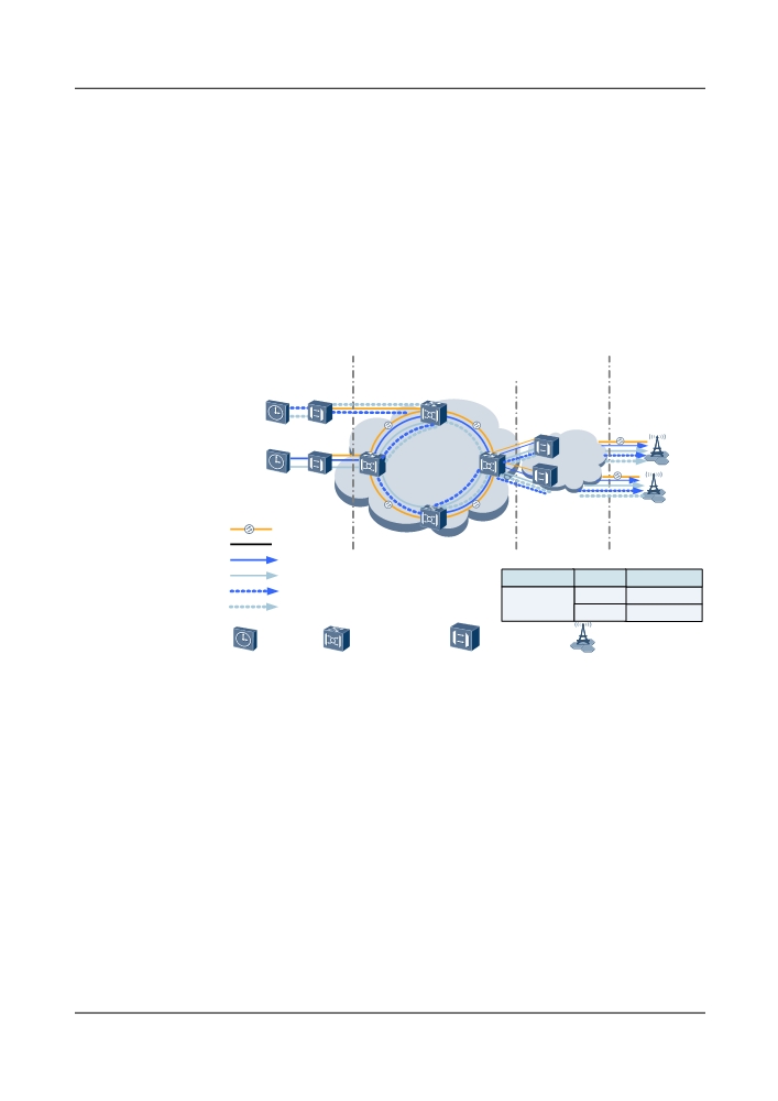
Application 1: Time transmission based on IEEE 1588v2-compliant frequency
synchronization and phase synchronization
As shown in Figure 5-45, the other device (such as the OptiX PTN device) obtains frequency
and phase signals from the BITS device and transmits the frequency and phase signals to the
connected OptiX OSN 8800 on the OTN network. On the other side of the OTN network, another
OptiX OSN 8800 transmits the frequency and phase signals to the two other devices (such as
OptiX PTN devices or OptiX OSN 1800) over GE services. After receiving the frequency and
phase signals, the two other devices (such as OptiX PTN devices or OptiX OSN 1800) send the
frequency and phase signals to the Node Bs over GE services. For details about the
configurations, see Example Description.
Figure 5-45 IEEE 1588v2-compliant time transmission over GE services (using OSC channels
over the OTN network)
Frequency/Phase Sources
Transport Network
Base Stations
East
West
GE
Slave
BITS
West
GE
A
East
GE
Master
E
OTN Network
BITS
B
D
F
East
C
West
GE
West
East
Optical Cables
Cables
1588v2 frequency synchronization route
1588v2 phase synchronization route
Sites
Direction
Board
1588v2 frequency synchronization protection route
East
1-11ST2-1
1588v2 phase synchronization protection route
A,B,C,D
West
1-11ST2-2
OptiX OTN
BITS
Other devices
Node B
product series
Figure 5-46 shows an example in which frequency and phase signals are received using 2M
external clocks and 1PPS+TOD and phase synchronization is implemented using the second
method (IEEE 1588v2-compliant frequency synchronization + IEEE 1588v2-compliant phase
synchronization).
Application 2: Time transmission based on physical clock frequency synchronization and
IEEE 1588v2-compliant phase synchronization
As shown in Figure 5-46, on one side of the OTN network two OptiX OSN 8800 obtain 2M
clock signals and 1PPS+TOD time signals from the master and slave BITS devices and send the
frequency and phase signals to other OptiX OSN 8800 on the network. On the other side of the
OTN network, after processing the frequency and phase signals using the ESC boards, the egress
OptiX OSN 8800 sends the frequency and phase signals to the connected other devices (such as
OptiX PTN devices or OptiX OSN 1800). Then, the other devices (such as OptiX PTN devices
or OptiX OSN 1800) send the frequency and phase signals to the Node Bs through their 2M
external ports and external time ports (1PPS+TOD ports). For details about the configurations,
see Example Description.
159
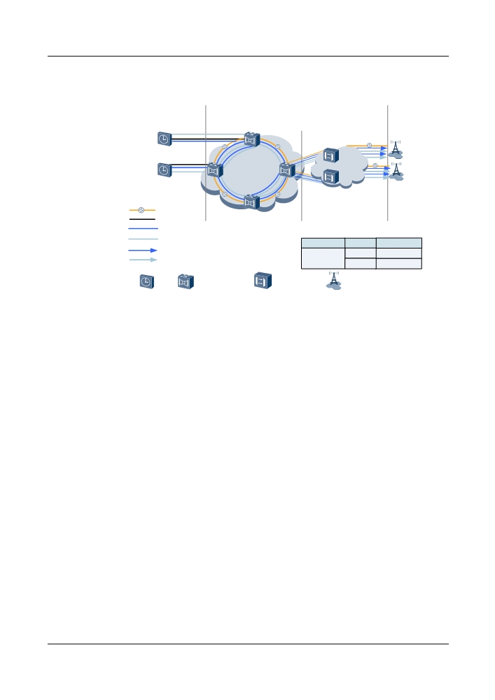
Figure 5-46 Physical clock frequency synchronization + IEEE 1588v2-compliant phase
synchronization using 2M clock and 1PPS+TOD ports (using ESC channels over the OTN
network)
Frequency/Phase Sources
Transport Network
Base Stations
2M/1PPS
East
West
+TOD
West
GE
A
East
E
E
B
OTN Network
D
2M/1PPS
F
+TOD
East
GE
C
West
West
East
Optical Cables
Cables
Physical synchronization route
1588v2 phase synchronization protection route
Sites
Direction
Board
Physical synchronization protection route
East
12-52ND2-1
1588v2 frequency synchronization protection route
A,B,C,D
West
12-52ND2-2
OptiX OTN
BITS
Other devices
Node B
product series
5.10 ASON Management
An automatically switched optical network (ASON) is a new-generation optical transmission
network.
With integration of SONET/SDH functionality, effective IP technology, large-capacity WDM/
OTN, and revolutionary network control software, ASON lays a foundation for flexible and
scalable next generation optical networks, which are easy to operate and manage, and less
expensive to operate.
Introducing ASON into WDM networks brings the following benefits:
l High reliability: Protection and restoration together improve network reliability and service
security.
l Easy to use: Network resources and topologies are easy to discover and end-to-end services
can be quickly created.
l Easy to manage: Trail resources are manageable and predictable, and services can be
automatically reverted to their original trails.
l Investment saving: A mesh network ensures higher resource usage and enables quick
expansion (plug-and-play).
l New service types: Service level agreement (SLA) ensures differentiated services.
WDM/OTN equipment is an effective service carrier. However, only the capability of carrying
services (on the transport plane) does not qualify WDM/OTN equipment as advanced and future-
oriented equipment, which also requires outstanding performance in bandwidth usage,
flexibility, manageability, maintainability, reliability, and protection capability. It has become
a trend to implement a control plane over the transport plane of the WDM/OTN equipment.
The limitations on the WDM/OTN equipment are removed after the ASON technology is
implemented on the WDM/OTN equipment. Because of the ASON technology, the WDM/OTN
160
equipment features high reliability, flexibility, bandwidth utilization, maintainability, and
manageability and supports different service levels and quick deployment of services. Further,
the operability of a WDM/OTN network is highly improved because of the features supported
by the ASON technology, such as automatic discovery of resources, traffic engineering, dynamic
bandwidth adjustment, and interconnection and communication technologies.
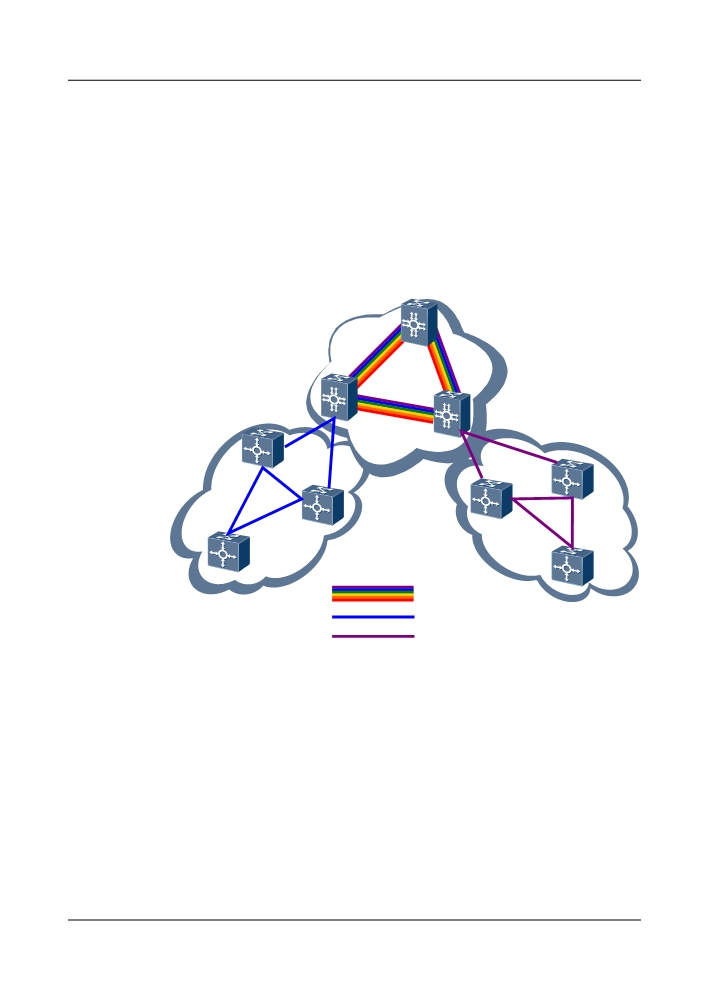
In addition, the OptiX OSN 8800 is also capable of cross-connecting services at the SDH layer.
Therefore, WDM ASON equipment can be networked with WDM ASON equipment or SDH
ASON equipment to enable cross-connections at multiple granularities and multiple layers, as
shown in Figure 5-47.
Figure 5-47 Flexible networking and multi-layer service cross-connections
OptiX OSN 8800
OptiX OSN 8800
Wavelength
OptiX OSN 8800
OptiX OSN 8800
OptiX OSN 9500
ODUk
VCk
OptiX OSN 8800
OptiX OSN 7500
OptiX OSN 6800
OptiX OSN 3500
Wavelength Link
ODUk Link
VCk Link
5.11 Transmission of Network Management Information
There are three communication modes: HWECC, OSI over DCC, IP over DCC.
l HWECC: The management information is transmitted by using the HWECC protocol
sharing method.
l IP over DCC management information is transferred by using the IP protocol sharing
method.
l OSI over DCC: The management information is transferred by using the OSI protocol
sharing method.
161
5.11.1 DCN Composition
DCNs are classified as internal and external DCNs.
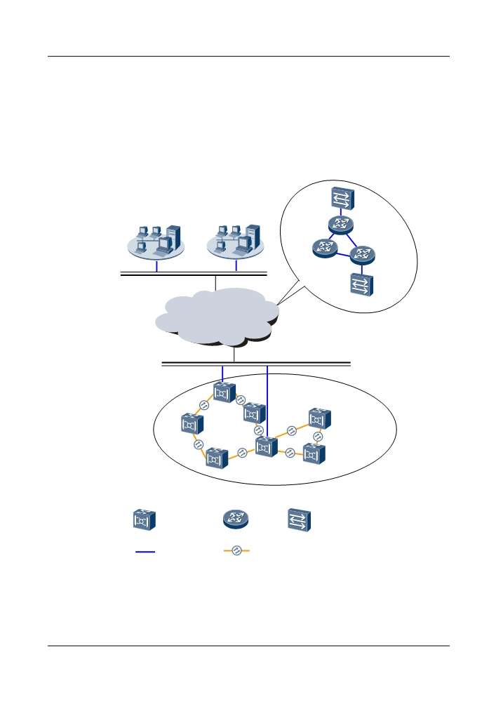
Both the U2000 and NEs are nodes of a DCN. The DCN between the U2000 and NEs is called
the external DCN, and the DCN between NEs is called the internal DCN, as shown in Figure
5-48.
Figure 5-48 DCN composition
Primary
Secondary
NMS
NMS
External DCN
Internal DCN
NG WDM
Ethernet
Router
equipment
switch
Network
Fiber
cable
l External DCN
On an actual network, the U2000 and NEs may be located on different floors of a building,
in different buildings, or even in different cities. Hence, an external DCN that is comprised
162
of the data communication equipment, such as LAN switches and routers, is required to
connect the U2000 and the NEs. As the external DCN involves knowledge of data
communication, no detailed description is provided in this document. The DCN mentioned
in this document refers to the internal DCN, unless otherwise specified.
l Internal DCN
On an internal DCN, the equipment supports the optical supervisory channel (OSC) and
the electrical supervisory channel (ESC) technologies to implement the DCN.
5.11.1.1 Optical Supervisory Channel Administration
The management information of the stations in the system is transmitted through the optical
supervisory channel (OSC).
Functions of the OSC
The optical supervisory channel (OSC) transmits the monitoring and management information
among the stations. The channel of the OSC is at 1491/1510/1511 nm.
The OSC boards include the HSC1, SC1, SC2 and ST2.
The OSC adopts CMI coding. If the signal rate is 2 Mbit/s before the coding, the signal rate is
4 Mbit/s after the coding. If the signal rate is 8 Mbit/s before the coding, the signal rate is 16
Mbit/s after the coding.
Working of the OSC
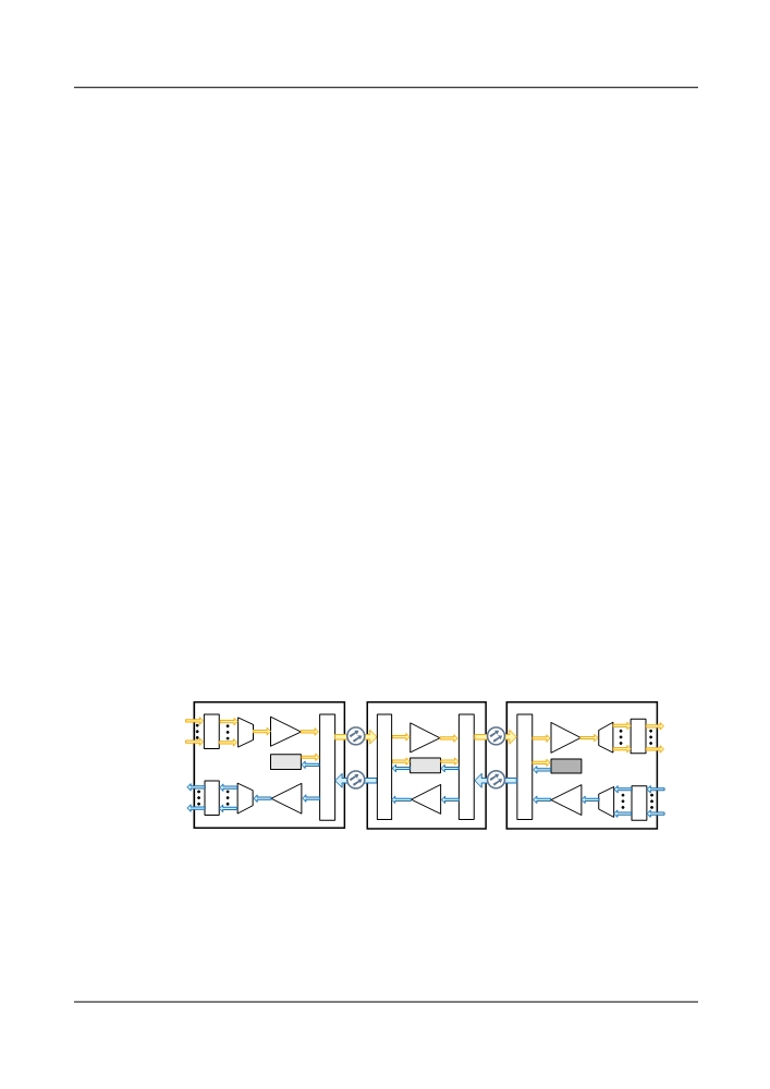
Figure 5-49 shows the signal flow of the OSC between three stations. The signals of the OSC
and the service signals are independent of each other. The supervisory signals are not amplified.
They are terminated and regenerated at a station.
The following takes the communication between the optical terminal multiplexer (OTM) and
the optical line amplifier (OLA) for example to describe the communication process of the OSC.
Figure 5-49 Signal flow of the OSC between three stations in chain networking
O
O
T
OM
OA
OA
OA
OD
T
U
U
F
F
F
F
SC1
I
I
I
I
SC2
SC1
U
U
U
U
O
O
T
OD
OA
OA
OA
OM
T
U
U
OTM1
OLA
OTM2
In the eastward direction, the HSC1/SC1 at OTM1 receives the overhead data frames from the
SCC. Then, the optical transmit module performs E/O conversion to the frames before the
supervisory data frames is modulated to the OSC wavelength (1510 nm). The multiplexer of the
FIU multiplexes the wavelength of the OSC with the service signals and sends them to the optical
regeneration station OLA.
163

The demultiplexer of the FIU at the OLA station demultiplexes the signals into service signals
and OSC signals. The service signals are transmitted to the east after they are regenerated and
amplified by the OAU.
The west optical receive module of the SC2 at the OLA performs O/E conversion to the OSC
signals. The supervisory data frames are recovered and processed before they are sent to the
SCC for data exchange. The east optical transmit module of the SC2 performs E/O conversion
for the processed supervisory signals. The OSC signals and the service signals are multiplexed
by the FIU and sent to the line for transmission.
The demultiplexer of the FIU at the OTM2 station demultiplexes the signals into service signals
and OSC signals. The west optical receive module of the HSC1/SC1 performs O/E conversion
to the OSC signals. The supervisory data frames are recovered and processed before they are
sent to the SCC for data exchange.
In the westward direction, the SCC performs the same process to transmit the required data.
Channel Types
Chan
Description
Bandwidth
Applicable Board
nel
Type
D1-
When receiving
12 x 64 kbit/s
DAS1/HSC1/SC1/SC2/
D3,
supervision information
ST2
D4-
from the SCC board, the
D12
OSC board encapsulates
the information into E1
frames defined in ITU-T
G.703 for further
transmission.
OSC_
OSC_18 is a newly
18 x 64 kbit/s
TN12SC1/TN12SC2
18
developed DCN channel
to improve the OSC
communication capacity.
FE_D
FE electrical ports are
10.24 Mbit/s (shared by
ST2/DAS1a
CN
used to transmit DCN
the OSC and ASON
information.
channels, each assigned
about 5 Mbit/s bandwidth)
a: The WSC port on the board is used to transmit DCN information.
5.11.1.2 Electrical Supervisory Channel Administration
The electrical supervisory channel (ESC) deletes the insertion loss of the FIU. This lowers the
cost and power budget of optical channels.
Functions of the ESC
In the OptiX OSN 8800 system, the monitoring and management information of each station
can be transmitted and communicated through the ESC. The OTU board, tributary board, and
line board realize the ESC transmission by using the DCC bytes or the associated GCC0/1/2
164
bytes compliant with ITU-T G.709. The external IP management information can be sent to the
system through the 10 Tbit/s or 100 Tbit/s Ethernet port and then carried by the ESC.
The OptiX OSN 8800 uses the GCC0 or GCC1+GCC2 bytes to achieve the ESC communication.
In this case, the bandwidth varies with the line rate, which is the rate of the OTU.
Working Mode of the ESC
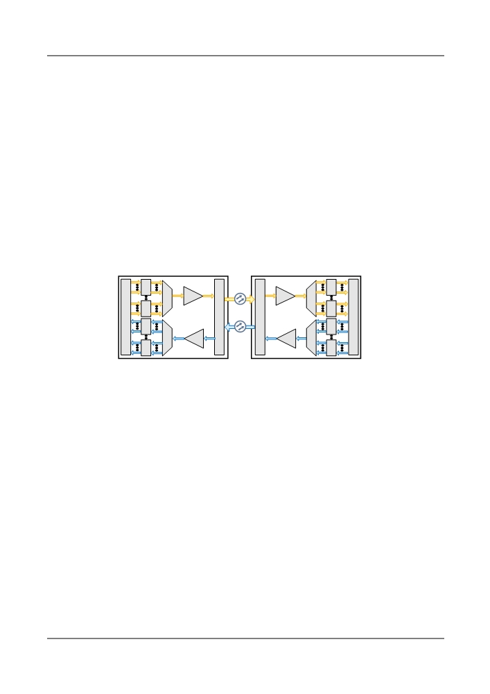
Figure 5-50 shows the signal flow of the ESC for two stations. As shown in the figure, all the
OTUs that support data communication network (DCN) communication at the transmit end
receive the DCN data from the SCC and then send the DCN data to the opposite station. At the
receive end, the SCC selects the DCN data automatically from one route according to the actual
situation. If the route is abnormal, the SCC automatically receives the DCN data from another
route.
The following uses the communication between two OTM stations as an example to describe
the communication of the ESC.
Figure 5-50 ESC signal flow in the chain networking
O
O
T
T
U
U
OA
OA
OM
OM
O
O
S
T
F
F
T
S
U
U
C
I
I
C
C
O
U
U
O
C
T
T
U
U
OD
OA
OA
OD
O
O
T
T
U
U
OTM1
OTM2
In the east, the SCC at OTM1 inserts the supervisory information into the DCN channel in the
overhead serial port according to a specific protocol such as the High-level Data Link Control
(HDLC) protocol. Then the supervisory information is sent to the OTN overhead processing
unit of the OTU through the 2M overhead serial port between the SCC and the OTU. The OTN
overhead is then sent to the line side.
The OTU at OTM2 extracts the overhead from the line side and sends the overhead to the OTN
overhead processing unit through the overhead serial port. The overhead is finally sent to the
SCC.
In the east, the SCC performs the reverse process.
5.11.2 Huawei DCN Solution
Huawei OptiX transmission equipment provides multiple DCN solutions, which will fit various
networks.
DCN Classification by NMS Access Mode
l Indirect access to the NMS: A non-gateway NE accesses the NMS through a gateway NE.
l Direct access to the NMS: An NE accesses the NMS as a gateway NE.
165

DCN Classification by Protocol
l HWECC Solution: When the networking is comprised of only the OptiX transmission
equipment, the HWECC solution is preferred. In this solution, NEs transmit the data that
supports the HWECC protocol through DCCs. The solution features easy configuration
and convenient application. As the HWECC protocol is a proprietary protocol, the
management problems cannot be solved when the networking is comprised of both the
OptiX equipment and the third-party equipment.
l IP over DCC Solution: When the networking is comprised of both the OptiX transmission
equipment and the third-party equipment that supports the IP over DCC function, the IP
over DCC solution is preferred. The IP over DCC solution can also be applied when the
networking is comprised of only the OptiX transmission equipment. In the IP over DCC
solution, NEs transmit the data that supports the TCP/IP protocol through DCCs. As the
TCP/IP protocol is a standard protocol, the management problems are solved when the
networking is comprised of both the OptiX equipment and the third-party equipment. The
configuration of the IP over DCC solution is more complicated than that of the HWECC
solution.
l OSI over DCC Solution: When the networking is comprised of both the OptiX transmission
equipment and the third-party equipment that supports the OSI over DCC function, the OSI
over DCC solution is preferred. In the OSI over DCC solution, NEs transmit the data that
supports the OSI protocol through DCCs. As the OSI protocol is a standard protocol, the
management problems are solved when the networking is comprised of both the OptiX
equipment and the third-party equipment. The configuration of the OSI over DCC solution,
however, is more complicated than the configurations of the HWECC solution and the IP
over DCC solution.
DCN Classification by Physical Resource
l Inband port: A DCN is built on service channels provided by equipment under management.
l Outband port: An outband port is a port (usually an Ethernet port) used for data transmission
between NEs on an ASON network. Without using a service path, data transmission can
be achieved by connecting this port to data communication equipment such as an Ethernet
switch or router.
l NMS port: An NMS port refers to the management network port on an NE.
l Transparent transmission: A transparent channel is provided on OTN equipment so that it
does not detect the intermediate network or link.
Table 5-24 lists details on the preceding DCN classifications.
Table 5-24 DCN solutions
Protocol
Indirect
Direct
Inband
Outband
NMS Port
Classificati
NMS
NMS
Port
Port
on
Access
Access
HWECC
Supported
Not
Supporteda
Supported
Supporteda
solution
supported
IP over DCC
Supported
Supported
Supported
Supported
Supported
solution
166

Protocol
Indirect
Direct
Inband
Outband
NMS Port
Classificati
NMS
NMS
Port
Port
on
Access
Access
OSI over
Supported
Supported
Not
Supported
Supported
DCC
supported
solution
l a: POS ports are not supported.
l b: Extended ECC is supported.
5.11.2.1 DCN Solution Classification by NMS Access Mode
Indirect NMS Access
In this mode, the NMS sends data to gateway NEs by running the IP or OSI protocol. When
receiving the data, the gateway NEs query the core route table at the application layer by NE ID
and then forward the data to NEs accordingly. Gateway NEs and non-gateway NEs can run the
HWECC, IP, or OSI protocol between themselves.
Direct NMS Access
In this mode, all forwarding NEs on the NMS access path query the IP route table or OSI route
table at the network layer by NE IP address or NSAP address and then forward data from the
NMS accordingly. This mode requires that the NMS and NEs are reachable to each other at the
network layer. That is, a ping test on the NE that is initiated on the NMS is successful.
NOTE
IP and OSI are applicable to the scenarios where Huawei WDM/OTN equipment is interconnected with third-
party equipment.
5.11.2.2 DCN Solution Classification by Protocol
HWECC Protocol
ITU-T G.784 defines the architecture of the ECC protocol stack based on the OSI seven-layer
reference model. The HWECC protocol stack is based on the ECC protocol stack.
The HWECC protocol consists of four layers: physical layer (DCC), media access layer, network
layer, and transmission layer. See Figure 5-51.
167
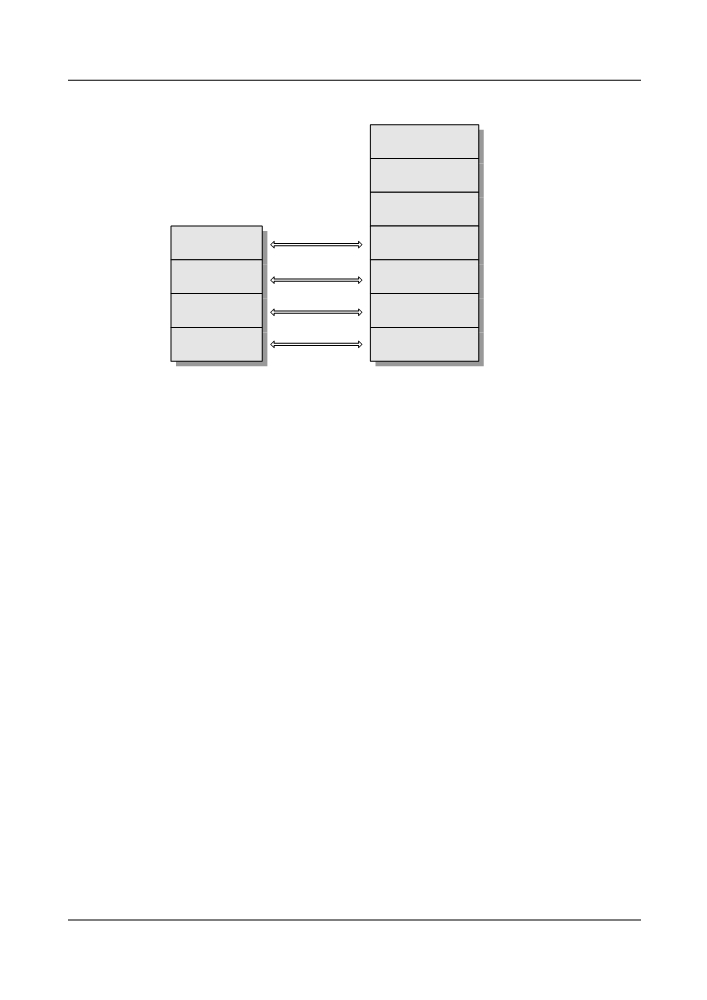
Figure 5-51 Architecture of the HWECC protocol stack
Application layer
Presentation layer
Session layer
Transport layer
Transport layer
Network layer
Network layer
Media access
Data link layer
layer
Physical layer
Physical layer
HW ECC
OSI model
protocol stack
l
Physical layer
The main function of the physical layer is to control physical channels. The physical layer
performs the following functions:
- Receives and sends data over the physical channels, including receiving data from
physical channels and transferring the data to the upper layer.
- Receives the data frames transferred from the upper layer and sends them to physical
channels.
The channels at the physical layer include DCC channels and extended ECC channels. The
physical layer can process the data frame with a maximum of 1024 bytes.
l
Media access layer
The media access layer is also called the medium access control (MAC) layer. The main
function of the MAC layer is to activate or close physical DCCs between the physical layer
and the network layer. The MAC layer shields the diversity of the physical networks and
provides the uniform service upwards (point-to-point physical channel). The MAC layer
performs the following functions:
- Establishes and maintains the MAC connection between adjacent NEs.
When there is a reachable physical channel between two adjacent NEs, the MAC layer
establishes a MAC connection between the NEs. Each MAC connection includes the
address of the opposite NE, the ID of the physical channel, the connection timer, and
other information.
- Provides the data communication service.
The MAC layer receives the data frame transferred from the physical layer. If the
destination address is the local station, the MAC layer transfers the data frame to the
network layer. Otherwise, the MAC layer discards the data frame.
The MAC layer sends the data frame from the network layer. If the destination address
of the data frame has a MAC connection, the MAC layer sends the data frame to the
168