HUAWEI OptiX OSN 8800 T64/T32 Intelligent Optical Transport Platform. Product Description - part 14
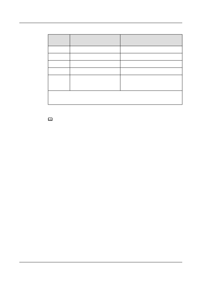
Table 5-14 OPU types and bit rates
OPU type
OPU Payload nominal bit
OPU Payload bit rate tolerance
rate
OPU0
238/239 × 1 244 160 kbit/s
±20 ppm
OPU1
2 488 320 kbit/s
±20 ppm
OPU2
238/237 × 9 953 280 kbit/s
±20 ppm
OPU3
238/236 × 39 813 120 kbit/s
±20 ppm
OPUflex for
client signal bit rate
client signal bit rate tolerance, with a
CBR client
maximum of ±100 ppm
signals
NOTE
The nominal OPUk Payload rates are approximately:1 238 954.310 kbit/s (OPU0), 2 488 320.000 kbit/s
(OPU1 Payload), 9 995 276.962 kbit/s (OPU2 Payload) and 40 150 519.322 kbit/s (OPU3 Payload).
NOTE
In Table 5-14, the ODUk consists of 3824*4 bytes. Each OPUk payload consists of 3808*4 bytes. The
238/239 of the OPU0 payload nominal rates indicate the ratio of the OPU0 payload to the ODU0 bytes.
The 238/237 and 238/236 of the OPUk payload nominal rates indicate the ratio of the OPUk payload to
the OPUk payload excluding the stuffing information. The supplementary description is as follows:
l OPU0: The ratio of the OPU0 payload to the ODU0 bytes is as follows: (3808*4)/(3824*4) = 238/239.
l OPU1: No stuffing information is added when the STM-16 is mapped to the OPU1 as payload.
l OPU2: 16 columns of stuffing information are added when the STM-64 is mapped to the OPU2 as
payload. Therefore, the ratio of the OPU2 payload to the OPU2 payload excluding the stuffing
information is as follows: (3808*4)/[(3808-16)*4] = 238/237.
l OPU3: 32 columns of stuffing information are added when the STM-256 is mapped to the OPU3 as
payload. Therefore, the ratio of the OPU3 payload to the OPU3 payload excluding the stuffing
information is as follows: (3808*4)/[(3808-32)*4] = 238/236.
5.7.3 ODUflex
The OptiX OSN 8800 supports the flexible optical data unit flexible (ODUflex) technique. Using
the ODUflex technique, the OptiX OSN 8800 can adapt itself to various services such as video,
storage, and data services, and is able to provide future IP services.
Introduction to ODUflex
OptiX OSN 8800 T64/T32/T16 of earlier versions supports only four types of ODUk mappings:
ODU0 (1.25G), ODU1 (2.5G), ODU2 (10G), and ODU3 (40G). Services can be mapped only
to fixed bandwidth. Therefore, service mapping is not flexible and bandwidth waste may result.
ITU-T defines ODUk with flexible bandwidth (ODUflex for short) to avoid bandwidth waste
caused by service mapping.
ODUflex has the following features:
l The bandwidth required for ODUflex is about N x bandwidth of each ODTUk timeslot (1
≤ N ≤ 8).
136
l The ODTUk timeslot is the basic unit of ODUk frames and each ODTUk timeslot has the
bandwidth of 1.25Gbit/s.
NOTE
l ODTUk timeslots are basic units of ODUk frame signals. That is, ODUflex signals consist of multiple
ODTUk timeslots. Each ODTUk timeslots provides 1.25 Gbit/s bandwidth. One ODU0 signal equals one
ODTUk timeslot and ODU1 signal equals two ODTUk timeslots.
For example, when a 3G-SDI service at a rate of 2.97 Gbit/s is received on the client side, the
bandwidth usage is as follows:
l When ODUflex is not used for service mapping, the mapping path is 3G-SDI -> ODU2 -
> OTU2. In this case, the service occupies all the bandwidth (10 Gbit/s) of ODU2 and
wastes about 7 Gbit/s bandwidth.
l When ODUflex is used for service mapping, the mapping path is 3G-SDI -> ODUflex ->
ODU2 -> OTU2. Only three ODTUk timeslots are occupied and the left five ODTUk
timeslots are available for other services. Each ODTUk timeslot provides 1.25 Gbit/s
bandwidth; therefore, 6.25 Gbit/s (5 x 1.25 Gbit/s) bandwidth is saved.
ODUflex Applications
l
Transport of generic CBR signals
ODUflex can be used to transmit constant bit rate (CBR) services on an optical transport
network (OTN). The services whose CBRs are higher than 2.48832 Gbit/s are mapped to
an ODUflex (CBR) container in bit synchronization mode. Functions such as end-to-end
performance monitoring and protection switching are feasible on the ODUflex (CBR)
container. The overheads and monitoring management modes of ODUflex services and
traditional ODUk (k= 0, 1, 2, 3) are the same. For the application scenarios, see Figure
5-33 and Figure 5-34.
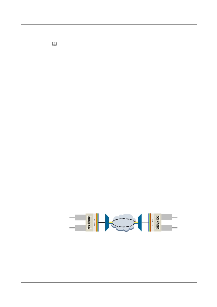
Figure 5-33 shows how ODUflex is used to transport generic CBR signals. An FC400
service occupies four ODTUk timeslots and is mapped to an ODUflex container; a 3G-SDI
service occupies three ODTUk timeslots and is mapped to an ODUflex container. In this
way, the FC400 and 3G-SDI services share the same OTU2 wavelength.
Figure 5-34 shows how ODU2 is used to transport generic CBR signals. The FC400 and
3G-SDI services are mapped to different ODU2 containers, and therefore they occupy
different OTU2 wavelengths.
Figure 5-33 Transport of generic CBR signals (ODUflex)
FC400 and 3G-SDI share a same OTU2 wavelength
FC400
FC400
(4 x ODTUk TS)
(4 x ODTUk TS)
ODUflex
ODUflex
OTU2
OTU2
OTN Network
3G-SDI
3G-SDI
(3 x ODTUk TS)
(3 x ODTUk TS)
ODUflex
ODUflex
Client side
WDM side
WDM side
Client side
137
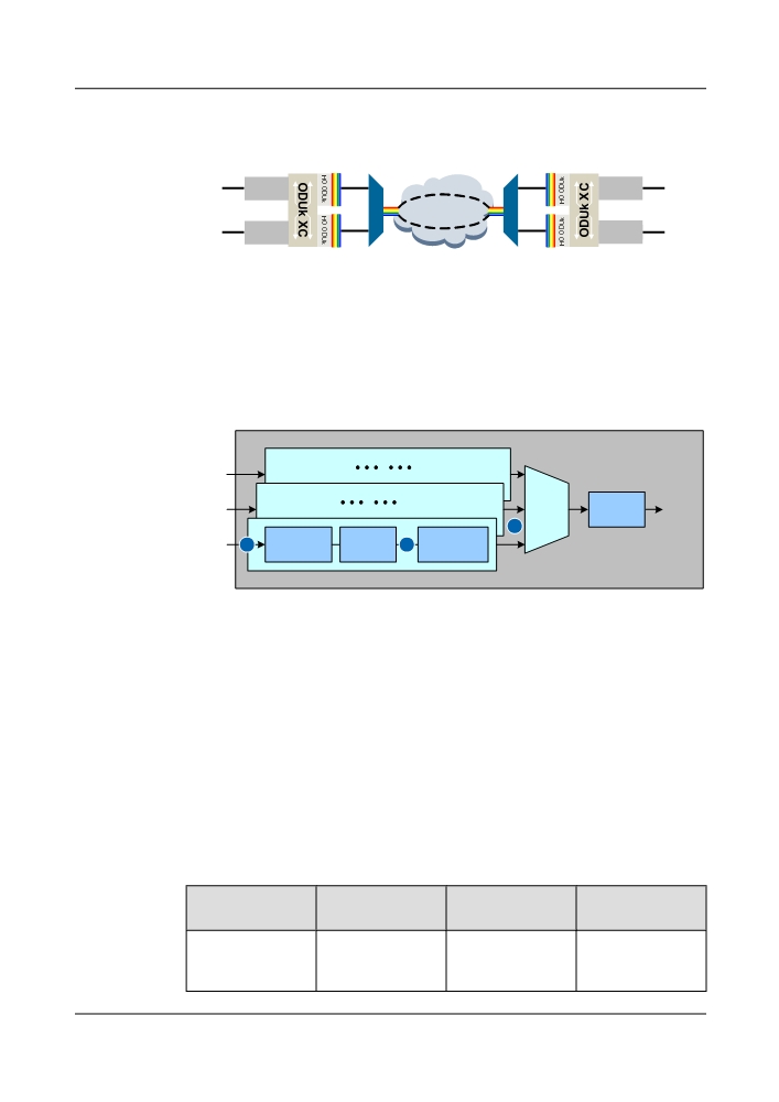
Figure 5-34 Transport of generic CBR signals (ODU2)
FC400 and 3G-SDI each occupy a OTU2 wavelength
Client
Line
Line
Client
FC400
OTU2
OTU2
FC400
ODU2
ODU2
OTN Network
3G-SDI
OTU2
OTU2
3G-SDI
ODU2
ODU2
Client side
WDM side
WDM side
Client side
ODUflex Implementation
Figure 5-35 shows how an ODUflex signal is mapped and multiplexed.
Figure 5-35 ODUflex mapping and multiplexing method
Client
ODUk.t
+ ODUk
ODUk
Service
s MUX
Overhead
3
BMP Mapping
+ ODUflex
GMP Mapping
1
2
into OPUflex
Overhead
into ODUk.ts
1.
The client signals are mapped into an OPUflex frame using the bit-synchronous mapping
procedure (BMP) or GPF-F mapping method. The OPUflex frame changes into an ODUflex
frame after it carries an ODUflex frame header.
2.
The ODUflex frame is mapped into N ODTUk timeslots by using the generic mapping
procedure (GMP).
3.
Multiple ODTUk timeslots are multiplexed into a standard ODUk frame after an ODUk
frame header is inserted.
ODUflex Signal Types
Table 5-15 lists the current boards that support transmission of signals through ODUflex frames.
Table 5-15 ODUflex signal transmission
Applicable Board
Encapsulation
Client Signal Type
ODUflex
Mode
Mapping Path
TN11LOA
ODUflex(CBR)
FC400/FC800/3G-
Client signal-
SDI
>ODUflex->ODU2-
>OTU2
138
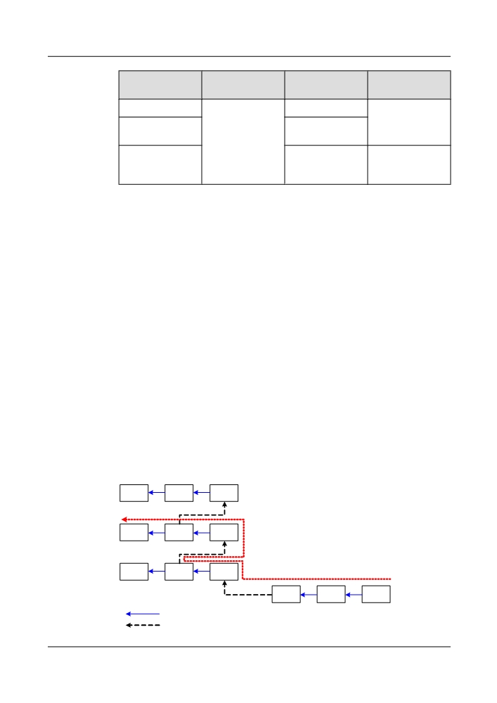
Applicable Board
Encapsulation
Client Signal Type
ODUflex
Mode
Mapping Path
TN54TOA
FC400/3G-SDI
Client signal-
>ODUflex
TN53TDX,
FC800
TN55TQX
TN53NQ2,
-
ODUflex->ODU2-
TN53ND2,
>OTU2
TN53NS2
5.7.4 Mapping and Multiplexing
This section describes how client signals are mapped and multiplexed on Huawei transport
equipment in addition to the mapping paths and required timeslots.
H-L Multiplexing Hierarchy
In the high-order (H) and low-order (L) multiplexing hierarchy, client signals in an OTN system
are sent to the line for transmission after the H-L multiplexing processes. For low-order
multiplexing, a client signal is multiplexed into a low order (LO) ODUk signal. For high-order
multiplexing, an LO ODUk signal is multiplexed into a high order (HO) ODUk signal, which
is then transmitted on the line. Before OptiX OSN 8800 V100R005, client signals are mapped
and multiplexed level by level. For example, to map a client signal into an ODU2 signal, the
client signal must go through the client->ODU0->ODU1->ODU2 process. However, in OptiX
OSN 8800 V100R005 and later versions, which support the H-L multiplexing hierarchy, the
mapping process is simplified as client->ODU0->ODU2.
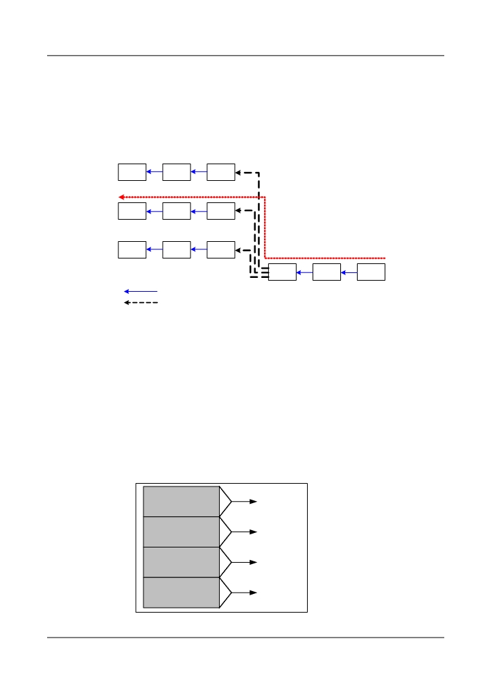
The following describes how the TN52TOG and TN52ND2 boards map and multiplex client
signals level by level using a GE signal as an example. To map the GE signal into an ODU2
signal before sending the signal into the cross-connect board, the equipment of a version earlier
than V100R005 must perform the client-> ODU0 ->ODU1->ODU2 process, which is marked
as red in Figure 5-36.
Figure 5-36 Level-by-level mapping and multiplexing
OTU3
ODU3
OPU3
x4
OTU2
ODU2
OPU2
x4
OTU1
ODU1
OPU1
x2
OTU0
ODU0
Client
Mapping
Multiplexing
139
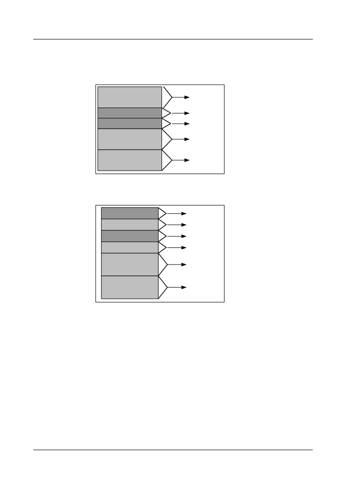
For the equipment of V100R006C01 or a later version, boards such as the LOA board support
H-L multiplexing and can map a client signal into an ODU2 signal according to the client-
>ODU0->ODU2 process. Then the equipment sends the ODU2 signal to the cross-connect
board. The H-L multiplexing process is marked as red in Figure 5-37.
Figure 5-37 H-L mapping and multiplexing
x32
OTU3
ODU3
OPU3
x8
OTU2
ODU2
OPU2
x2
OTU1
ODU1
OPU1
OTU0
ODU0
Client
Mapping
Multiplexing
Mixed Mapping and Multiplexing
The equipment supports mapping and multiplexing of lower order ODUk signals into higher
order ODUk signals. For example, the equipment can map and multiplex a mixture of ODU0
and ODU1 signals into an ODU2 frame.
Each ODUk frame occupies some TS sub-timeslots. TS sub-timeslots may be occupied in the
following modes:
l Completely fixed consecutive occupation: Each ODUk signal occupies a fixed TS sub-
timeslot if hybrid mapping or multiplexing is not supported. For example, the second ODU1
channel occupies TS3 and TS4.
ODU2
ODU1
TS1-TS2
(First channel)
ODU1
TS3-TS4
(Second channel)
ODU1
TS5-TS6
(Third channel)
ODU1
TS7-TS8
(Fourth channel)
140
l Initially fixed consecutive occupation: The fixed occupation relationships will be changed
after hybrid mapping and multiplexing are supported. For example, ODU1 may occupy
TS5 and TS6.
ODU2
ODU1 (first channel)
TS1-TS2
ODU0 (first channel)
TS3
ODU0 (second channel)
TS4
ODU1 (second channel)
TS5-TS6
ODU1 (third channel)
TS7-TS8
l Flexible and inconsecutive occupation: Timeslots are assigned more flexibly. For example,
the first ODU1 channel occupies TS2 and TS4, which are inconsecutive timeslots.
ODU2
ODU0 (first channel)
TS1
ODU1 (first half of the first
TS2
channel)
ODU0 (second channel)
TS3
ODU1 (second half of the
TS4
first channel)
ODU1 (second
TS5-TS6
channel)
ODU1 (third channel)
TS7-TS8
5.7.5 TCM
Tandem connection monitoring (TCM) is used mainly when the network scale is relatively large
or when network resources are leased to different network carriers. In this case, the TCM is used
to monitor the quality of the transmission channels in a specific network area, for example, a
leased transmission network.
The TCM provides section monitoring for the ODUk (k = 0, 1, 2, 3) channel. The main functions
of TCM are as follows:
l Monitoring the tandem connection between optical UNI and UNI, and monitoring the
ODUk connection that traverses public transport network. Users monitor the quality of the
provider network with TCM, which is enabled at the interface nearest to the provider
network.
l Monitoring the tandem connection between optical NNI and NNI, and monitoring the
ODUk connection that passes through carrier network. The network provider monitors the
141
quality of local network with TCM, which is located at the interfaces on both ends of the
provider network.
l Monitoring the tandem connection of optical channels for fault location or verification of
service delivery quality.
TCM overheads are allocated in three ways: concatenation, embedding, and overlaying. OTU
frame overheads include six levels of TCM overheads, from TCM1 to TCM 6, providing the
following subfields:
l Trial trace identifier (TTI)
l bit interleaved parity 8 (BIP-8)
l Backward defect indication (BDI)
l Backward error indication and backward incoming alignment error (BEI/BIAE)
l Status bits STAT, such as LTC and LCK
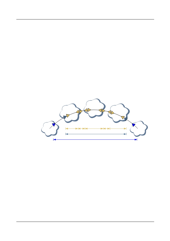
The functions of TCM in the network are shown in Figure 5-38. When client services are carried
by different carrier networks, TCM overheads can be used to monitor the network quality.
Figure 5-38 Example of TCM functions
Operator B
network
Operator A
Operator A
network
network
Domain and domain interconnect supervision (TCM3)
User
User
network
Lead operator QoS supervision (TCM2)
network
User QoS supervision (TCM1)
In this example, three levels of TCM overheads are used to supervise different networks.
l The user uses TCM1 to achieve QoS supervision between optical UNI and UNI.
l The lead operator uses TCM2 to achieve QoS supervision over operator networks.
l Operator A and Operator B use TCM3 to achieve QoS supervision over the local domain
and domain interconnection.
5.7.6 FEC Function
Certain OTUs, tributary boards and line boards have forward error correction (FEC) function
and advanced forward error correction (AFEC) function.
With the FEC and AFEC functions, the OSNR requirements of the system are less at the receive
end. This extends the transmission distance between the optical amplifier section and the
regenerator section.
In addition, the FEC and AFEC help to reduce bit error rate during the transmission. It also
enhances the transmission quality of DWDM networks.
142
l Standard FEC technology of the OTN network increases the FEC overheads by 7% and
realizes encoding gain 6.2 dB (BER = 1E-15).
l AFEC technology of the OTN network increases the FEC overheads by 7% and realizes
encoding gain more than 8 dB (BER = 1E-15).
NOTE
Boards that use different FEC modes cannot interoperate with each other.
5.8 WDM Technologies
This chapter describes the WDM technologies and functions implemented on the OptiX OSN
8800 T32/8800 T64.
5.8.1 DWDM and CWDM Technical Specifications
The OptiX OSN 8800 T32/8800 T64 supports two wavelength division multiplexing
technologies: dense wavelength division multiplexing (DWDM) and coarse wavelength division
multiplexing (CWDM) technologies. This section describes the technical specifications and
transmission capacity of the product using the two technologies.
There are no limits for wavelengths transmitted over G.652, G.654, and G.655 fibers used with
the OptiX OSN 8800 T32/OptiX OSN 8800 T64. To realize 40-wavelength transmission, the
wavelengths transmitted over G.653 fiber should be within 196.05 THz to 194.1 THz.
l DWDM includes 40-wavelength system and 80-wavelength system. The wavelengths are
in the C band compliant with ITU-T G.694.1.
- Each C-band 40-wavelength system with a channel spacing of 100 GHz can transmit a
maximum of 40 wavelengths. It supports services of 2.5 Gbit/s, 10 Gbit/s and 40 Gbit/
s.
- Each C-band 80-wavelength system with a channel spacing of 50 GHz can transmit a
maximum of 80 wavelengths. It supports services of 10 Gbit/s and 40 Gbit/s.
- C-band 80-wavelength systems consist of even and odd wavelengths. The information
about odd and even wavelengths is provided below:
- C_EVEN: indicates even-numbered wavelengths. In total there are 40 even
wavelengths. The center frequency of the even wavelengths is within the range of
192.100 THz to 196.000 THz (center wavelength is within the range of 1529.55 nm
to 1560.61 nm) and the frequency spacing is 100 GHz.
- C_ODD: indicates odd-numbered wavelengths. In total there are 40 odd
wavelengths. The center frequency of the odd wavelengths is within the range of
192.150 THz to 196.050 THz (center wavelength is within the range of 1529.16 nm
to 1560.20 nm) and the frequency spacing is 100 GHz.
- The 40-wavelength system can be upgraded to the 80-wavelength system smoothly.
l CWDM with a channel spacing of 20 nm can access up to eight wavelengths. It only applies
to services rated at 2.5 Gbit/s. The wavelengths are in the C band compliant with ITU-T
G.694.2.
DWDM wavelengths can be transported in the window of CWDM 1531 nm to 1551 nm to
expand the CWDM system capacity. Figure 5-39 shows the expansion of wavelength allocation.
With this expansion scheme, a CWDM system can transmit a maximum of 26 DWDM
wavelengths at 100 GHz channel spacing. If the DWDM wavelength is 50 GHz in channel
spacing, a CWDM system can transmit a maximum of 50 DWDM wavelengths.
143
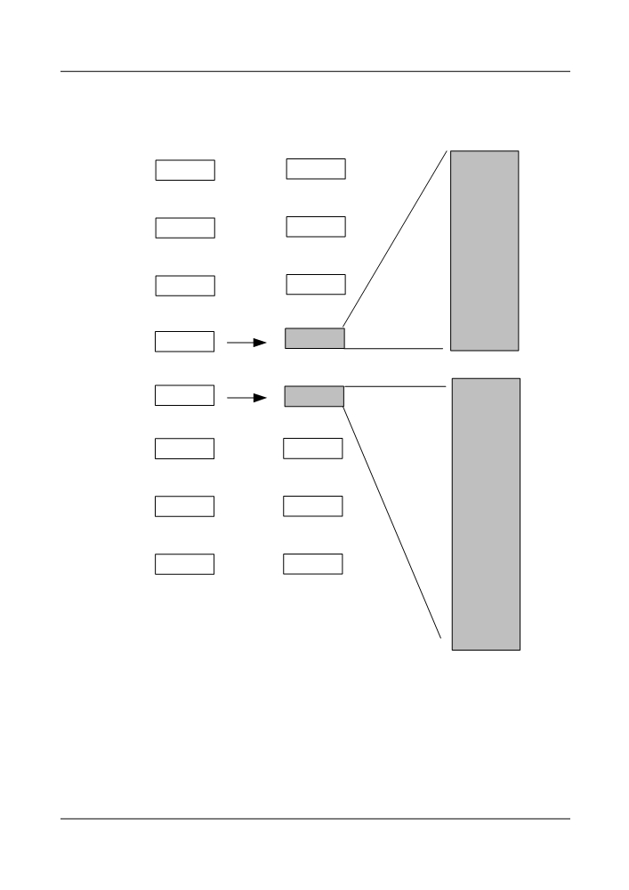
Figure 5-39 DWDM wavelength expansion and allocation in the CWDM system
CWDM
DWDM
DWDM over CWDM
wavelengths
wavelengths
1529.55nm
1471nm
1471nm
1530.33nm
1531.12nm
1531.90nm
1491nm
1491nm
1532.68nm
1533.47nm
1511nm
1534.25nm
1511nm
1529.55nm
1535.04nm
-
1536.61nm
1535.82nm
1531nm
10λ
1535.61nm
1545.32nm
1551nm
16λ
1546.12nm
1545.32nm
1546.92nm
-
1547.72nm
1571nm
1571nm
1557.36nm
1548.51nm
1549.32nm
1550.12nm
1591nm
1591nm
1550.92nm
1551.72nm
1552.52nm
1553.33nm
1611nm
1611nm
1554.13nm
1554.94nm
1555.75nm
1556.55nm
1557.36nm
Figure 5-40 shows the equipment configuration in which DWDM wavelengths are transported
in the window of CWDM 1531 nm to 1551 nm. The DWDM wavelengths need to pass through
the DWDM MUX/DEMUX and CWDM MUX/DEMUX. Hence, the optical amplifier unit
needs to be configured in between.
144
Figure 5-40 Application of the DWDM wavelength in the CWDM system
OTU
OTU
OA
MUX/
MUX/
DEMUX
DEMUX
OTU
OA
MO M1
OTU
MO M1
CWDM
DWDM
5.8.2 Nominal Central Wavelength and Frequency of the DWDM
System
Table 5-16 Wavelengths and frequencies of a C-band 80-channel (spacing of 50 GHz) system
Wavele
Central
Central
Wavele
Central
Central
ngth
Frequency
Wavelength
ngth
Frequency
Wavelength
No.
(THz)
(nm)
No.
(THz)
(nm)
1
196.05
1529.16
41
194.05
1544.92
2
196.00
1529.55
42
194.00
1545.32
3
195.95
1529.94
43
193.95
1545.72
4
195.90
1530.33
44
193.90
1546.12
5
195.85
1530.72
45
193.85
1546.52
6
195.80
1531.12
46
193.80
1546.92
7
195.75
1531.51
47
193.75
1547.32
8
195.70
1531.90
48
193.70
1547.72
9
195.65
1532.29
49
193.65
1548.11
10
195.60
1532.68
50
193.60
1548.51
145

Wavele
Central
Central
Wavele
Central
Central
ngth
Frequency
Wavelength
ngth
Frequency
Wavelength
No.
(THz)
(nm)
No.
(THz)
(nm)
11
195.55
1533.07
51
193.55
1548.91
12
195.50
1533.47
52
193.50
1549.32
13
195.45
1533.86
53
193.45
1549.72
14
195.40
1534.25
54
193.40
1550.12
15
195.35
1534.64
55
193.35
1550.52
16
195.30
1535.04
56
193.30
1550.92
17
195.25
1535.43
57
193.25
1551.32
18
195.20
1535.82
58
193.20
1551.72
19
195.15
1536.22
59
193.15
1552.12
20
195.10
1536.61
60
193.10
1552.52
21
195.05
1537.00
61
193.05
1552.93
22
195.00
1537.40
62
193.00
1553.33
23
194.95
1537.79
63
192.95
1553.73
24
194.90
1538.19
64
192.90
1554.13
25
194.85
1538.58
65
192.85
1554.54
26
194.80
1538.98
66
192.80
1554.94
27
194.75
1539.37
67
192.75
1555.34
28
194.70
1539.77
68
192.70
1555.75
29
194.65
1540.16
69
192.65
1556.15
30
194.60
1540.56
70
192.60
1556.55
31
194.55
1540.95
71
192.55
1556.96
32
194.50
1541.35
72
192.50
1557.36
33
194.45
1541.75
73
192.45
1557.77
34
194.40
1542.14
74
192.40
1558.17
35
194.35
1542.54
75
192.35
1558.58
36
194.30
1542.94
76
192.30
1558.98
37
194.25
1543.33
77
192.25
1559.39
38
194.20
1543.73
78
192.20
1559.79
39
194.15
1544.13
79
192.15
1560.20
146