HUAWEI OptiX OSN 8800 T64/T32 Intelligent Optical Transport Platform. Product Description - part 12
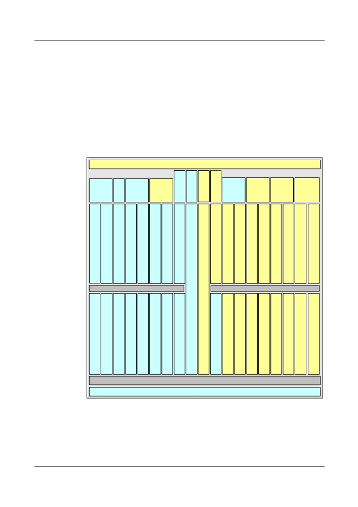
5.4.1.5 OptiX OSN 8800 T32 DC Input Protection
The power supply system of an OptiX OSN 8800 T32 subrack uses four power supply boards
to separately provide -48 V/-60V power inputs for the two sections of the subrack.
The power supply system supports four -48 V/-60 V DC power inputs for mutual backup in
OptiX OSN 8800 T32 subrack. The power supply system adopts the switched-mode power
supply mode for two areas, that is, the blue-slot area and the yellow-slot area, as shown in Figure
5-17. Each area is configured with a pair of power supplies of mutual backup: one pair is IU39
and IU45, and the other pair is IU40 and IU46. The normal operation of the equipment is not
affected in the case of failure of any external input -48 V/-60V power supply. Figure 5-17 shows
the two pairs of power supplies of mutual backup.
Figure 5-17 Power distribution and supply for the OptiX OSN 8800 T32 subrack
FAN IU51
AUX
STG
STG
EFI2
EFI1
PIU
PIU
PIU
PIU
STI
ATE
IU43
IU37
IU38
IU39
IU40
IU41 IU42
IU44
IU45
IU46
IU47
IU48
SCC
IU20
IU21
IU22
IU23
IU24
IU25
IU26
IU27
IU29
IU30
IU31 IU32
IU33
IU34 IU35
IU36
IU28
XCH
XCH
/
/
XCM
XCM
IU9
IU10
SCC
IU1
IU2
IU3
IU4
IU5
IU6
IU7
IU8
IU12
IU13 IU14
IU15
IU16 IU17
IU18
IU19
IU11
FAN IU50
5.4.1.6 Redundancy Protection for Fans
In the OptiX OSN 8800 T32 system, each subrack has two fan areas. In the OptiX OSN 8800
T64 system, each subrack has four fan areas. And each fan area has three fans for heat dissipation.
114

The speed of each fan can be adjusted independently and the failure of any fan does not affect
the other fans.
5.4.1.7 Inter-Subrack Communication Protection
Subracks of an NE can be cascaded in various modes. When subracks are cascaded to form a
ring, the NE provides working and protection Ethernet communication channels for
communication between the master and slave subracks. In this case, when the working channel
is faulty, services are switched to the protection channel, achieving protection for inter-subrack
communication.
5.4.2 Network Level Protection
OptiX OSN 8800 T32/8800 T64 provides various network protection schemes, including WDM
protection schemes and a great variety of data service protection schemes.
For principles of the protections, refer to the Feature Description.
The security and survivability of a network can be further enhanced through an automatic
switched optical network (ASON), which is generally referred to as intelligent optical network.
As a main networking mode of ASON, mesh features high flexibility and scalability. On a mesh
network, to make the interrupted services available, you can immediately restore the services
through the rerouting mechanism in addition to the traditional protection scheme such as 1+1
protection and shared protection scheme such as ODUk SPRing. That is, the mesh network can
support traditional protection schemes, dynamic restoration of services, and service restoration
mechanisms in case of protection failures. In this manner, services are not interrupted if the
resources are available.
For principles of the ASON protections, refer to the ASON User Guide.
5.4.2.1 WDM Protection
The OptiX OSN 8800 T32/8800 T64 provides various types of WDM protection, as listed in
Table 5-8.
For principles of the protections, refer to the Feature Description.
Table 5-8 WDM protection
Category
Sub-Category
Description
Optical line
Optical line
It uses the dual fed and selective receiving function of the
protection
protection
OLP board to protect line fibers between adjacent stations
by using diverse routing.
Optical
Client-side 1+1
It uses the dual fed and selective receiving function of the
channel
protection
OLP/DCP/SCS board to protect the OTU and the OCh
protection
fibers.
Intra-board 1+1
It uses the dual fed and selective receiving function of the
protection
OTU/OLP/DCP board to protect the OCh fibers by using
diverse routing.
115

Category
Sub-Category
Description
SNCP
SW SNCP
The intra-board cross-connections on the TOM board
Protection
implement the dual fed and selective receiving function.
In this manner, the SW SNCP protection protects the OCh
fiber.
ODUk SNCP
It uses the dual fed and selective receiving function of the
protection
electrical layer grooming to protect the line board and the
OCh fibers. The cross-connect granularity is ODU0
signals, ODU1 signals, ODU2 signals and ODU3 signals.
Tributary
Protects the tributary service by using the dual-fed and
SNCP
selectively-receiving function at the electrical cross-
connect layer. The cross-connect granularity is ODU0
signals, ODU1 signals, ODU2 signals and ODU3 signals.
VLAN SNCP
Uses the dual-fed selective receiving function of a L2
protection
module to protect Ethernet services. The protection
granularity is the service with VLAN.
ODUk
ODUk SPRing
It applies to the ring network with distributed services.
SPRing
protection
This protection uses two different ODU1 or ODU2
protection
channels to achieve the protection of multiple services
between all stations.
OWSP
OWSP
It applies to the ring networks. This protection uses two
different wavelengths to achieve the protection of one
wavelength of service between all stations.
ASON
Optical-layer
Protects services of OCh wavelength level.
protection
ASON
Electrical-layer
Protects services of ODUk wavelength level.
ASON
5.4.2.2 SDH Protection
The OptiX OSN 8800 T32/8800 T64 provides various types of SDH protection, as listed in
Table 5-9.
For details on the working principle of each type of protection, see the Feature Description.
Table 5-9 Service protection classifications
Category
Subcategory
Description
Linear MSP
1+1 linear MSP
It realizes dual transmitting and selective
receiving by using two fibers. In this manner, it
provides protection for the services on the link.
1:N (N ≤ 14) linear
It protects services by providing one protection
MSP
fiber for N working fibers.
116

Category
Subcategory
Description
MSP Ring
Two-fiber
In this protection mode, half of the capacity of
bidirectional MSP
the fibers in each transmission direction is
ring
assigned to the service channel, and the other
half of the capacity is assigned for the protection
channel. The service timeslot and protection
timeslot in each direction are transmitted over
the same fiber. That is, the service signals and
protection signals are transmitted at the same
time over the same fiber.
Four-fiber
In this protection mode, two fibers are used in
bidirectional MSP
the transmit and protection directions. One of the
ring
fibers in each direction is used to transmit the
working service, and the other fiber is used to
transmit the protection service.
Transoceanic MSP
A transoceanic MSP ring can be a two-fiber bidirectional MS shared
Ring
protection ring or a four-fiber bidirectional MS shared protection ring.
When the network fails, the ring path is switched between the source
and sink nodes of the service rather than on two adjacent nodes of the
failed node to avoid multiple transoceanic events of the services, which
increase the delay of transmission in the long-haul transmission
network (for example, the marine system).
SNCP
In this protection mode, the service protection is implemented by means
of dual transmitting and selective receiving. That is, the services are
dual transmitted at the source but selectively received at the sink.
Sub-network
The SNCTP provides the protection path at the VC-4 level. When the
connection tunnel
working path is faulty, all its services are switched to the protection
protection
path.
(SNCTP)
Ethernet protection
Ethernet ring
This protection type is based on the traditional
protection
Ethernet mechanism and uses the Ethernet
operation, administration, and maintenance
(OAM) function and ring network automatic
protection switching (R-APS) protocol to realize
quick protection switching in the Ethernet ring
network.
LCAS
This protection type dynamically adjusts the
number of virtual containers required for service
mapping to provide protection for virtually
concatenated services.
LAG
In this protection mode, multiple links that are
connected to the same equipment are bundled
together to increase the bandwidth and improve
link reliability.
117

Category
Subcategory
Description
STP/RSTP
When the STP or RSTP is started, it logically
modifies the network topology to avoid a
broadcast storm. The STP or RSTP realizes link
protection by restructuring the topology.
MSTP
In the case of the Ethernet user network where
loops exist, the MSTP generates the tree
topology according to VLAN IDs of the Ethernet
packets. Thus, the broadcast storm is avoided
and the network traffic is balanced according to
the VLAN IDs of the Ethernet packets.
DLAG
The distributed link aggregation group (DLAG)
is a board-level port protection technology used
to detect unidirectional fiber cuts and to
negotiate with the opposite end. In the case of a
link down failure on a port or a hardware failure
on a board, the services can automatically be
switched to the slave board, thus realizing 1+1
protection for the inter-board ports.
ASON protection
Protects services of STM-N, VC-4, VC-3.
5.4.2.3 Data Protection
The OptiX OSN 8800 T32/8800 T64 provides various types of data protection, as listed in Table
5-10.
For details on the working principle of each type of protection, see the Feature Description.
Table 5-10 Data protection
Protect
Description
ion
DBPS
DBPS protection works with Ethernet ring protection to protect the links between
protecti
Ethernet boards and BRAS, and also protect services at 10GE and GE ports on
on
Ethernet boards.
Etherne
Based on the traditional Ethernet mechanism and APS protocol specific to a ring
t ring
network, Ethernet ring protection achieves fast protection switching of an Ethernet
protecti
ring network.
on
LAG
An LAG binds multiple links on the same equipment, increasing the bandwidth
and improving link reliability.
STP and
When the STP or RSTP is running, it modifies the logical network topology to
RSTP
avoid a broadcast storm. The RSTP can achieve link protection by restructuring
the network topology.
118
Protect
Description
ion
MSTP
In the case of a user Ethernet network with a loop, MSTP can generate a tree
topology by VLAN IDs of Ethernet packets to avoid a broadcast storm, and can
also achieve load sharing by VLAN IDs of user packets.
LPT
The link state pass through (LPT) is used to detect and report the faults that occur
at the service access node and in the intermediate transmission network. The LPT
notifies the equipment at two ends in the transmission network of starting the
backup network at the earliest time for communication, thus making sure the
normal transmission of the important data.
5.5 Data Characteristics
The OptiX OSN 8800 T32/8800 T64 supports the Ethernet features and mainly supports the
following Ethernet services: EPL, EVPL (QinQ), and EPLAN.
5.5.1 Service
The OptiX OSN 8800 T32/8800 T64 supports the Ethernet private lien (EPL), Ethernet private
local area network (EPLAN), and Ethernet virtual private line (EVPL, or QinQ) services. It saves
bandwidth resources while achieving dynamic sharing of Ethernet services among multiple
points.
EPL Service
The EPL services can also be classified into the EPL service based on port and the EPL service
based on port plus VLAN.
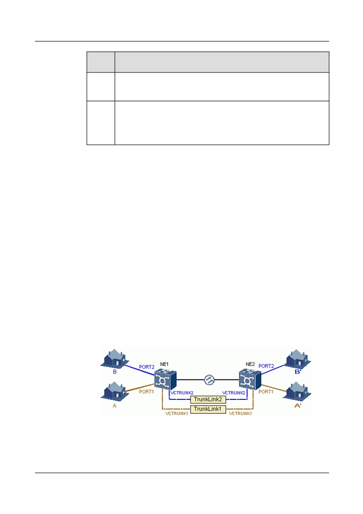
l EPL service based on port is intended for point-to-point transparent transmission of
Ethernet services. As shown in Figure 5-18, the Ethernet services from different NEs are
transmitted to the destination node through separate VCTRUNKs. Then the data from
different NEs can be transmitted in a reliable and secure manner.
Figure 5-18 EPL service based on port
l EPL service based on port plus VLAN is intended for convergence of Ethernet services.
For this type of an EPL service, a specific port or VCTRUNK can be shared. When a specific
port is shared by multiple services, the port resources can be saved, as shown in Figure
119
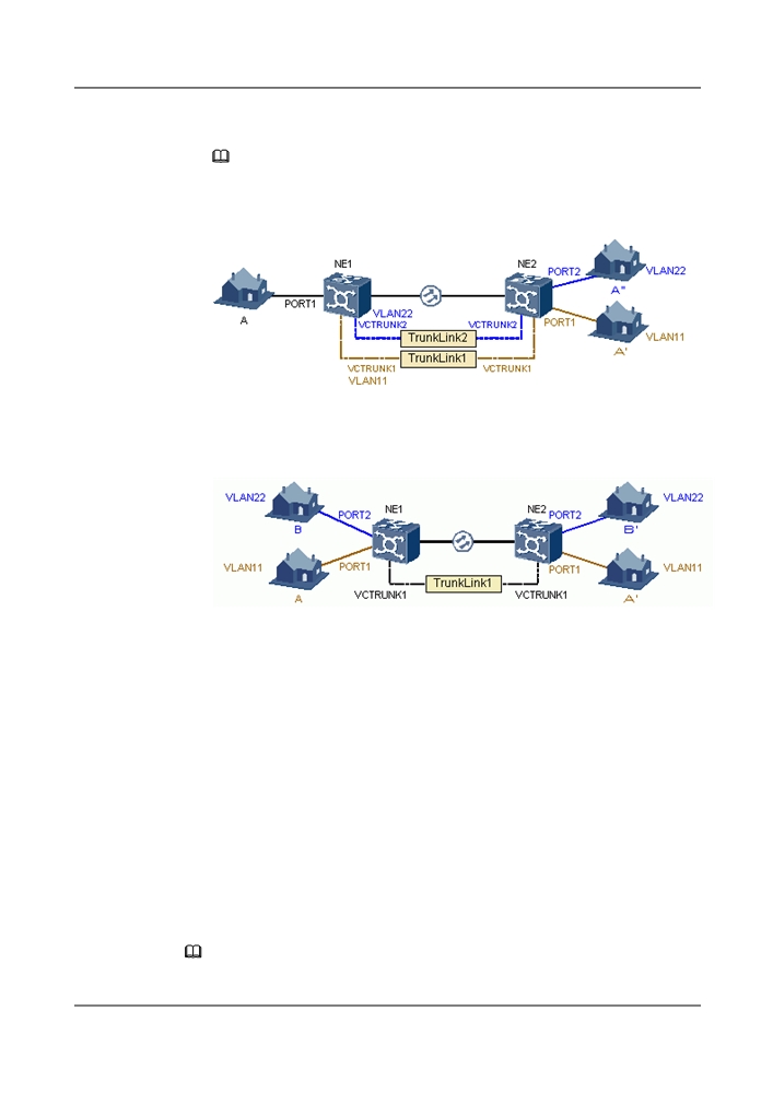
5-19. When a specific VCTRUNK is shared by multiple services, the VCTRUNK resources
can be saved, as shown in Figure 5-20.
NOTE
On the NE, the number of VLAN services cannot exceed 32768.
Figure 5-19 Port-shared EPL service
Figure 5-20 VCTRUNK-shared EPL service
EPLAN Service
The OptiX OSN 8800 T32/8800 T64 supports Layer 2 switching of Ethernet data, that is,
EPLAN.
The concept of virtual bridge or various bridge (VB) is originally presented by Huawei.
According to the definition, each VB adopts an independent configuration mode. Each VB uses
one VLAN but different VBs may use the same VLAN.
In the system, one or more VBs can be set up on each NE and a MAC address table can be
created on each VB. The MAC address table for each VB can be updated through system self-
learning. Then the accessed data can be transmitted through different VCTRUNKs according to
the destination MAC addresses.
The EPLAN service is intended to dynamically share Ethernet services at multiple points. The
EPLAN service conforms to the dynamic feature of data services and saves the bandwidth
resources. For details, see Figure 5-21.
NOTE
On the NE, the number of VLAN services cannot exceed 32768.
120
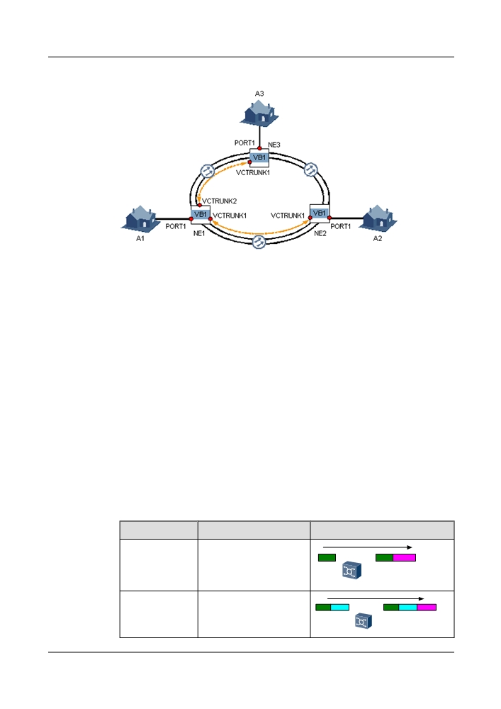
Figure 5-21 EPLAN service
EVPL (QinQ) Service
The EVPL (QinQ) service is intended to achieve "VLAN ID in VLAN ID". As the number of
network users continues to increase, the original VLAN IDs are not sufficient. The EVPL (QinQ)
service can solve this problem by identifying users with multi-layer VLAN IDs, and extending
VLAN IDs.
As a LAN technology, VLAN develops with the Ethernet switch technology. As the Ethernet
technology is widely used on networks (MAN Ethernet) of operators, using IEEE 802.1q VLAN
IDs to identify users and isolate the data is restricted. According to IEEE 802.1q, the VLAN tag
field contains only 12 bytes, which can indicate a maximum of 4,000 VLANs. In the MAN
Ethernet, however, the number of users far exceeds this maximum number.
To increase the number of VLANs, the QinQ technology is developed. According to the QinQ
technology, an IEEE 802.1q tag is attached to an IEEE 802.1q packet to increase the number of
VLAN IDs to 4,000 x 4,000. With the development of the MAN Ethernet and the requirements
of operators on elaborate operation, the QinQ technology can be used in more scenarios. The
inner and outer tags indicate different information. The inner tag (the C-VLAN) indicates the
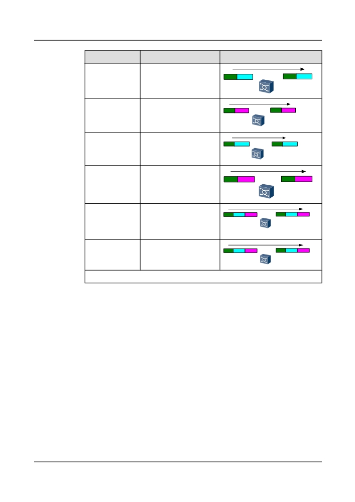
client, and the outer tag (the S-VLAN) indicates the service. For details, see Table 5-11.
Table 5-11 EVPL (QinQ) service
Operation
Description
Illustration
Sticking (and
The SVLAN tag is stuck (and
Data
Data
S-VLAN
stripping) the
stripped) based on thr port.
SVLAN tag
Sticking (and
The SVLAN tag is stuck (and
Data
C-VLAN
Data
C-VLAN
S-VLAN
stripping) the
stripped) based on the port
SVLAN tag
and CVLAN.
121
Operation
Description
Illustration
Transparently
The CVLAN tag is
Data
C-VLAN
Data
C-VLAN
transmitting the
transparently transmitted.
CVLAN tag
Transparently
The SVLAN is transparently
Data
S-VLAN
Data
S-VLAN
transmitting the
transmitted.
SVLAN tag
Switching the
The CVLAN tag is switched
Data
C-VLAN1
Data
C-VLAN2
CVLAN tag
based on the port.
Switching the
The SVLAN tag is switched
SVLAN tag
based on the port.
Data
S-VLAN1
Data
S-VLAN2
Transparently
The CVLAN+SVLAN tag is
Data
C-VLAN
S-VLAN
Data
C-VLAN
S-VLAN
transmitting the
transparently transmitted.
CVLAN+SVLAN
taga
Switching the
The SVLAN tag is switched
Data
C-VLAN
S-VLAN1
Data
C-VLAN
S-VLAN2
SVLAN taga
based on port+CVLAN
+SVLAN.
a: The EGSH board does not support this type of service.
Transit EVPL (MPLS) Service
Transit EVPL (MPLS) service is the service with MPLS tag switching and forwarding.
The service packets that are forwarded by the router should pass through the network that consists
of the OptiX OSN 8800 T32/8800 T64 equipment. To transparently transmit the service packets
that are transmitted from the PE router, the OptiX OSN 8800 T32/8800 T64 equipment create
an end-to-end tunnel on the PE routers. In details, the PE routers function as the ingress and
egress nodes, and the OptiX OSN 8800 T32/8800 T64 equipment functions as transit node.
5.5.2 QoS
Quality of service (QoS) defines the expected class of service, in terms of bandwidth, delay,
delay variation, and packet loss ratio, which should be guaranteed under all circumstances in a
communication network. This ensures that the request and response of an application meets the
expected class of service.
On a traditional IP network, all packets are treated the same way. Every router uses the first in
first out (FIFO) policy to process packets, and makes its best effort to transmit packets to the
destination; however, packet transmission performance, such as reliability and delay, are not
ensured.
122
To support voice, video, and data services that have different service requirements, a network
must be able to differentiate communication types and provide relevant service.
For a transmission where prioritized queues are used to support QoS, one of the egress queues
is set as a strict-priority (SP) queue, so that packets in this queue are always groomed with the
highest priority. This setting meets the requirements of key service packets. The other egress
queues adopt the weighted round robin (WRR) grooming algorithm so that packets in each queue
can obtain a certain period of service.
The Ethernet service processing boards provide the QoS function. By providing dedicated
bandwidths, lowering the packet loss ratio, and reducing the packet transmission delay and delay
jitter, the QoS function helps provide different classes of service for different customers.
The QoS function complies with the following standards: IETF RFC2697, RFC2698, RFC2309,
RFC2597, RFC2598, and IEEE802.1p.
5.5.3 OAM
The OptiX OSN 8800 T32/8800 T64 provides rich OAM functions to monitor services, detect
faults, and identify faults at each service layer.
5.5.3.1 ETH-OAM
ETH-OAM improves the Ethernet Layer 2 maintenance method and provides powerful
maintenance functions for service connectivity verification, deployment commissioning, and
network fault location.
The ETH-OAM is a protocol based on the MAC layer. It checks Ethernet links by transmitting
OAM protocol packets. The protocol is independent from the transmission medium. The OAM
packets are processed only at the MAC layer, having no impact on other layers on the Ethernet.
In addition, as a low-rate protocol, the ETH-OAM protocol occupies low bandwidth. Therefore,
this protocol does not affect services carried on the link.
Comparison between ETH-OAM and the maintenance and fault locating method on the existing
network:
l The current frame test method is based on only the encapsulation format where the same
type of data is contained. This test method is not applicable to other encapsulation formats
(such as GFP encapsulation format and HDLC encapsulation format) where different types
of data is contained.
l The current port loopback function focuses on all packets at the port. The loopback cannot
be performed for a specific service selectively.
l ETH-OAM can detect hardware faults.
l ETH-OAM can detect and locate faults automatically.
Huawei Ethernet service processing boards realize the ETH-OAM function that complies with
IEEE 802.1ag and IEEE 802.3ah. The combination of IEEE 802.1ag and IEEE 802.3ah provides
a complete Ethernet OAM solution.
The IEEE 802.1ag OAM function can be achieved through the continuity test, loopback test,
link trace test, and OAM_Ping test.
l The link trace (LT) test is used to locate the faulty point.
l The loopback (LB) is used to test the link state bidirectionally.
123
l The continuity check (CC) is used to test the link state unidirectionally.
l The OMA_Ping test is used to test the in-service packet loss ratio and hold-off time.
IEEE 802.3ah OAM is realized through the OAM auto-discovery, link performance detection,
fault locating, remote loopback, self-loop test, and loop port shutdown.
l The OAM auto-discovery is used to check whether the opposite end supports the IEEE
802.3ah OAM protocol.
l The link performance monitoring is used to monitor the BER performance.
l The fault detection is used to detect faults and inform the opposite end of the detected faults.
l The remote loopback is used to locate fault test the link performance.
l The self-loop test is used to test the self-loop ports.
l The loop port shutdown is used to block self-loop ports to solve the port loop problems.
5.5.3.2 RMON
Remote monitoring (RMON) is intended to monitor performance of Ethernet ports (ports and
VCTRUNK) and collect performance data for fault detection and performance reporting.
RMON supports Ethernet statistics groups and history Ethernet groups as follows:
l Ethernet statistics group: supports real-time statistics and query of packet length and packet
status at an Ethernet port.
l History Ethernet group: supports statistics and query of history performance data such as
packet length and packet status at an Ethernet port. This enables a user to query the history
statistics data at an Ethernet port in a given period.
5.5.3.3 Test Frame
Test frames are data packets used to test connectivity of a network that carries Ethernet services.
Test frames are mainly used to commission Ethernet services during deployment and identify
faults of Ethernet services.
Test frames can be encapsulated in GFP packets. The test frames on interconnected boards must
be encapsulated in the same format.
l GFP packets: GFP management frame format. The packets are sent along the same path as
GFP management frames.
5.6 Optical Power Management
The optical power management includes IPA, IPA of Raman System, IPA of PID, ALC, APE
, EAPE, OPA and AGC.
With the IPA, IPA of Raman System, IPA of PID, ALC, APE, EAPE, OPA and AGC functions,
the WDM equipment of Huawei OSN series provides optical power equalization of all channels,
groups of channels and a particular channel.
For details of the optical power management, see the Feature Description.
124