HUAWEI OptiX OSN 8800 T64/T32 Intelligent Optical Transport Platform. Product Description - part 13
5.6.1 Introduction to IPA
The system provides the intelligent power adjustment (IPA) function. When there is a fiber break
on the line, the upstream optical amplifier is shutdown to prevent exposed optical fibers hurting
human body. After the system is recovered, the optical amplifier works normally again.
In a DWDM system, optical fiber break, equipment failure or optical connector removal may
lead to the loss of optical signals. The system provides the IPA function to prevent exposed
optical fibers from harming the human body, especially the eyes, and to avoid a surge on an
optical amplifier. The system can locate and detect where the loss of optical power signals
happens on one or more optical sections on the main optical channel and the optical supervisory
channels. When this occurs it instantly shuts down the upstream optical amplifier. When optical
signals of the system are recovered, normal operation of the optical amplifier is restored.
5.6.2 Introduction to IPA of the Raman System
The power of the pump light from Raman amplifiers is very high. In a system configured with
Raman amplifiers, it is suggested that you configure and enable the IPA function before you
turn on a Raman amplifier. After a fiber cut is detected, shut down the Raman amplifier. As a
result, there is not a strong pump light sent from the LINE interface on the amplifier and the
optical power of the entire line remains at a safe level.
In a DWDM system, optical fiber break, equipment failure or optical connector removal may
lead to the loss of optical signals. The system provides the IPA function to prevent exposed
optical fibers from harming the human body, especially the eyes, and to avoid a surge on an
optical amplifier. The system can locate and detect where the loss of optical power signals
happens on one or more optical sections on the main optical channel and the optical supervisory
channels. When this occurs it instantly shuts down the upstream optical amplifier. When optical
signals of the system are recovered, normal operation of the optical amplifier is restored.
5.6.3 Introduction to ALC
The system provides the automatic level control (ALC) function. When the ALC function is
enabled, the increase in the line attenuation in a section causes a decrease in the input power of
the amplifier in that section. Its output power remains the same. The input and output power of
the downstream amplifiers remains the same.
Optical fiber aging, optical connector aging, or manual factors may lead to abnormal loss of
transmission lines in a DWDM system. When the loss on a line segment increases, all input and
output power is reduced on all downstream amplifiers. The system OSNR deteriorates. At the
same time, the received optical power will also be reduced, and the receiving performance will
be greatly affected. The closer the attenuated segment is to the transmission end, the greater is
the influence on OSNR. Figure 5-22 shows the power changes on optical line amplification
regenerators in case of abnormal loss on optical fiber lines.
If the system power with ALC function, this effect can be minimized. As the loss on a line
segment is increased, the input power on the amplifier is reduced. Due to ALC, the output power
as well as the input and output powers of other downstream amplifiers is not changed, which
result in less influence on the OSNR. The optical power received by the receiver is not changed.
Figure 5-23 shows the power changes on the optical line amplification regenerators in ALC
mode when there is abnormal loss on optical fiber lines.
125
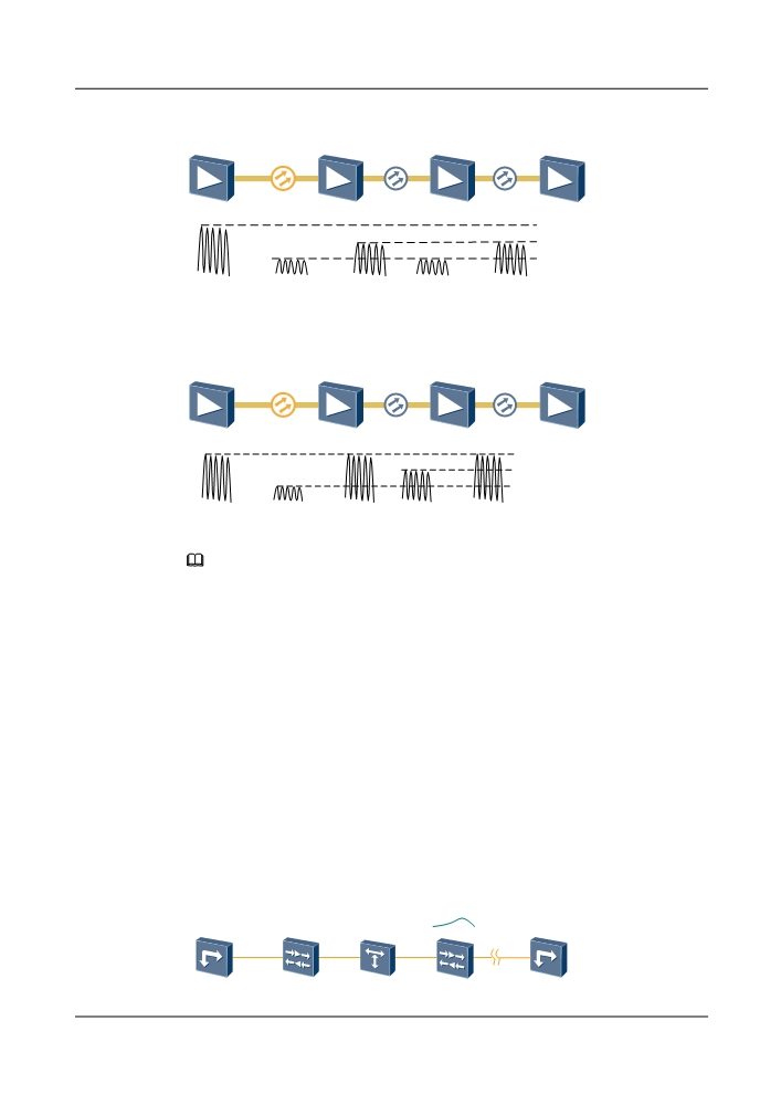
Figure 5-22 System power without ALC
High line losses
Normal output
Attenuated output
Attenuated input
Figure 5-23 System power with ALC
High line losses
Normal output
Normal input
Attenuated input
NOTE
Normally, two elements might cause the input power change in the optical amplifier:
l The addition and reduction of access channels (multiple channels might be added or dropped at the
same time).
l The abnormal loss in the physical media.
5.6.4 Introduction to APE
The automatic power equilibrium (APE) function automatically detects and adjusts the optical
power along channels on WDM-side ports to ensure the required channel optical power flatness.
If the channel optical power varies and flatness is not maintained to a specified requirement, the
OSNR of the optical transmission line will deteriorate, which will degrade and possibly interrupt
the communication.
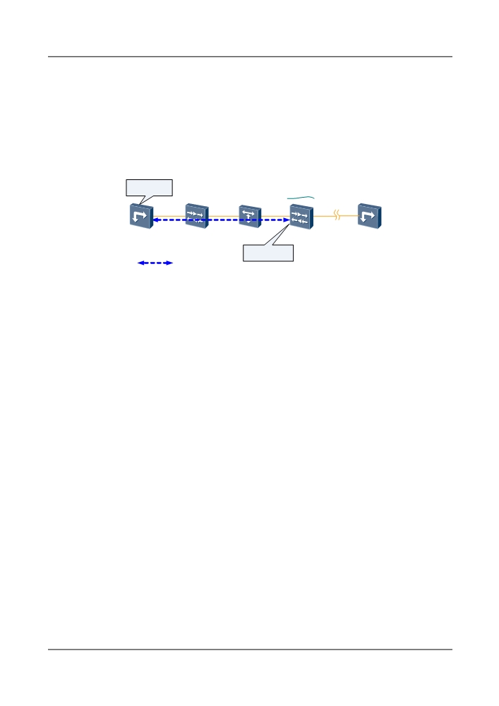
In practical applications of a WDM system, the channel optical power flatness at the receive end
may differ greatly from the channel optical power flatness achieved during the deployment
process when there is a change in fiber conditions, as shown in Figure 5-24.
Figure 5-24 Change in the channel optical power flatness at the receive end (APE not applied)
Optical power
flatness
Transmit end
OLA
OADM
Receive end
OTM
126
When the optical power of channels at the receive end is unbalanced, the optical power of the
channels must be adjusted to ensure the required optical power flatness. However, manually
adjusting the optical power is not only complex but also has high requirements on users.
The APE function can be used to automatically balance optical power to ensure a certain flatness
of the channel optical power, as shown in Figure 5-25.
Figure 5-25 Change in the channel optical power flatness at the receive end (APE applied)
Optical power
Adjusts channel
optical power
flatness
Transmit end
OLA
OADM
Receive end
OTM
(Adjustment site)
(Detection site)
Detects channel
optical power
Communication
channel between NEs
As shown in the figure above, the APE function applies to both the transmit and receive ends of
the signal. The transmit and receive ends exchange APE protocol frames using an NE
communication channel to deliver APE instructions and advertise APE execution results.
l At the receive end (detection site), the detection unit automatically detects the optical power
of each channel. If the optical power does not meet the requirement, the detection unit
delivers an instruction to the adjustment site requesting the adjustment site to adjust the
channel optical power.
l At the transmit end (adjustment site), the adjustment unit automatically adjusts channel
optical power after receiving the optical power adjustment instruction and informs the
detection site of the power adjustment result.
5.6.5 Introduction to EAPE
The system provides the enhanced automatic power pre-equilibrium (EAPE) function. EAPE
adjustment can be enabled to ensure that the receive-end signal quality of each channel meets
the preset requirement and that the services are available.
During the operation of a DWDM system, when service signals travel over a certain distance,
the OSNR of each channel of the DWDM system declines. As a result, the quality of the signals
at the receive end does not meet the design requirement. In this case, EAPE adjustment can be
enabled to ensure that the receive-end signal quality of each channel meets the preset requirement
and that the services are available.
5.6.6 Introduction to OPA
The optical power adjustment (OPA) technology is available in the commissioning phase.
In the commissioning phase, after the boards work normally, set the rated optical power values
of OA boards, create the optical cross-connections, and set Power Adjustment Mode to
Auto on the U2000. The software makes calculations, and the internal variable attenuator of the
adjustable board in the cross-connection path is adjusted automatically. The automatic
127
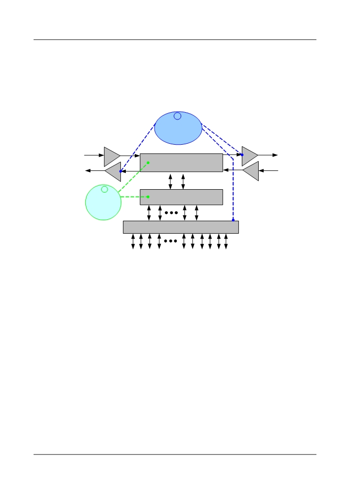
adjustment ensures that the input power of the OTU board and OA board meet the commissioning
requirements.
Figure 5-26 shows the principle of the OPA function. In the figure, 1 shows that the internal
variable attenuator of the adjustable board is adjusted, and 2 shows that the input power of the
OTU board and OA board meets the commissioning requirements.
Figure 5-26 Principle of the OPA function
2
Optical power
meet the
requirements of
boards
OA
OA
ROADM boards
OA
OA
1
Adjust optical
MUX/ DEMUX boards
power
automatically
OTU boards
5.6.7 Introduction to AGC
The system uses the automatic gain control (AGC) function to implement per-channel gain so
that the gain of a channel is locked regardless of how many optical wavelengths are transported
in a fiber. In this manner, the gain of a channel remains unchanged after one or more channels
are added or dropped, or when optical signal fluctuation occurs in one channel.
The Erbium-doped fiber amplifier (EDFA) used by the system works in the gain locking mode.
In this mode, the output optical power of the amplifier changes with the input optical power and
the gain is maintained. When the number of wavelengths changes, the power adjustment time
is within 1 ms in the gain locking mode so that the optical power of other channels remains
unaffected, and a burst bit error can be avoided during the process of adding or dropping
wavelengths.
The EDFA adopted by the system works in the gain locking mode. The amplifier is embedded
with the forward and backward feedback control loops, which dynamically respond to the change
of input optical power. When the change is less than 1 dB, the backward feedback control loop
is enabled to control the power precisely. When the change is more than 1 dB, the forward
feedback control loop is enabled to adjust the power rapidly.
By virtue of the gain locking mode, the system can transmit a single wavelength of signals and
also add or drop wavelengths without affecting services. Due to the embedded suppression
mechanism of the amplifier, if the services suddenly change or the amplifier degrades over a
certain hop, the services over other hops are not affected.
128
In the extreme situation where only one wavelength is normal and other wavelengths disappear
in the system, the AGC function can ensure that the services over this wavelength are not
affected.
l In the 40-wavelength system, the transmitting optical power of each channel is +4 dB.
When 39 of the 40 wavelengths disappear, the remaining one is not affected.
l In the 80-wavelength system, the transmitting optical power of each channel is +1 dB.
When 79 of the 80 wavelengths disappear, the remaining one is not affected.
The gain locking mode is more effective than the power locking mode in terms of power
efficiency because the pump optical power is always exported according to the utmost capacity
of the system, regardless of the actual number of working wavelengths.
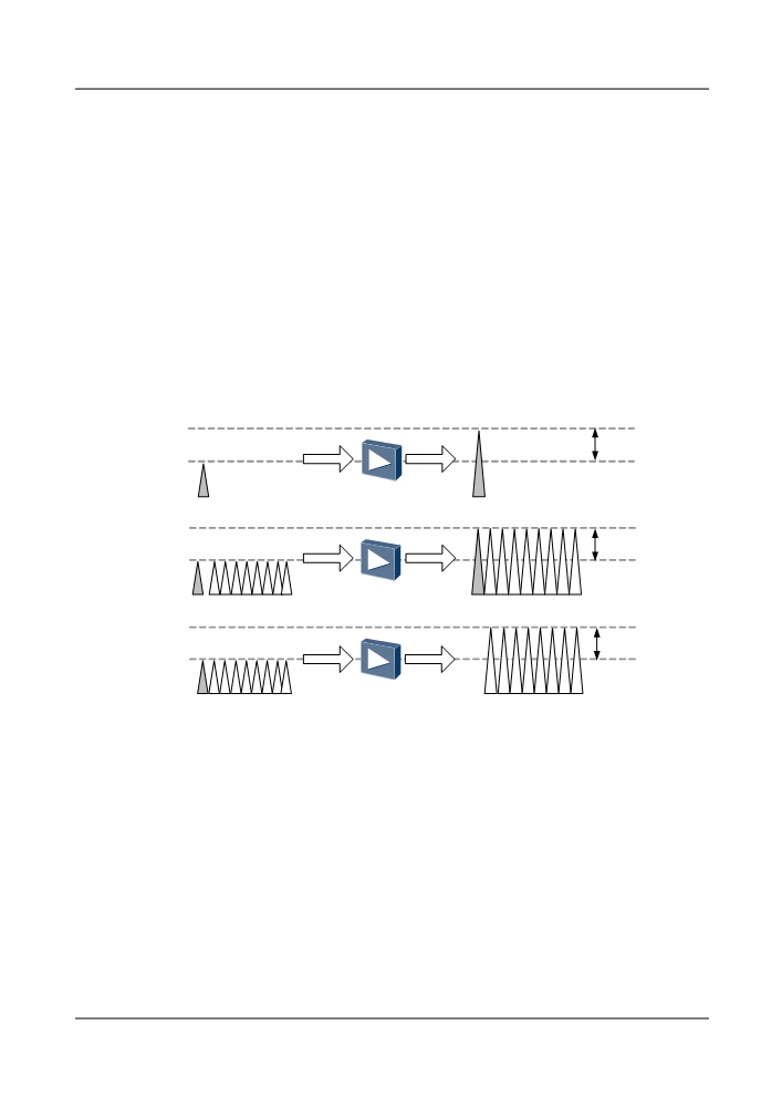
When the number of wavelengths is changing, AGC would ensure the optical power of remain
channels is not affected. It helps to avoid an outburst of bit errors when adding or dropping
channels from the main stream. As shown in Figure 5-27.
Figure 5-27 AGC function implementation
Gain
add
Gain is
Gain
wavelength
unchanged
drop
Gain is
Gain
wavelength
unchanged
All optical amplifier boards of OptiX WDM equipment work in AGC mode. The AGC function
is automatically enabled. You do not need to configure it on the U2000.
5.7 OTN Technologies
OTN technologies cover electrical-layer access, optical-layer access, mapping, multiplexing,
cross-connection, and protection.
5.7.1 Frame Format
This section describes the basic structure of an OTN interface and inclusion relationships on
OTN information structure.
129
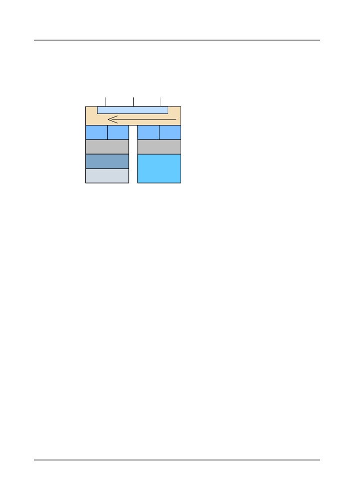
Basic Structure of the OTN Interfaces
Figure 5-28 shows the basic structure of the OTN interfaces.
Figure 5-28 Basic structure of the OTN interfaces
Client signal (for example, STM-N, ATM, IP,
Ethernet, OTN ODUk)
OPUk: Optical channel payload unit-k
OPUk
ODUk: Optical channel data unit-k
ODUkP
ODUkP: ODUk which provides end-to-end path supervision
ODUk
ODUkT
ODUkT: ODUk which provides tandem connection monitoring
OTUk: Completely standardized optical channel transport unit-k
OTUkV
OTUk
OTUkV
OTUk
OTUkV: Functionally standardized optical channel transport unit-
k
OCh
OChr
Och: Optical channel with full functionality
Ochr: Optical channel with reduced functionality
OMS: Optical multiplex section
OMSn
OTS: Optical transmission section
OPSn
OPS: Optical physical section
OTM: Optical transport module
OTSn
OTM-n.m Full
OTM-0.m, OTM-nr.m
functionality OTM
Reduced functionality
interface
OTM interface
OTM Principal Information Containment Relationships
The optical transport module (OTM-n[r].m) is the information structure of the OTN. The indexes
n and m define the number of supported wavelengths and bit rates at the OTN interfaces. The
index r represents reduced function. Two OTM structures are defined: OTM with full
functionality (OTM-n.m) and OTM with reduced functionality (OTM-0.m, OTM-nr.m).
l OTM with full functionality: OTM-n.m, consists of up to n multiplexed optical channels
and an OTM overhead signal (OOS). The OOS, including the optical channel overhead,
optical multiplexing section overhead, and optical transmission section (OTS) overhead,
is transmitted through the optical supervisory channel (OSC). The OTM-n.m information
structure is used to the OTS layer connections in the OTN. Figure 5-29 shows the principal
containment relationships of the OTM-n.m.
130
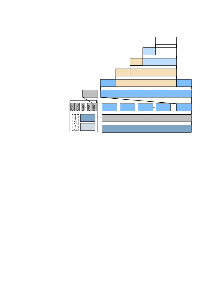
Figure 5-29 OTM-n.m principal containment relationships
Client signal
OPUk
OPUk
OPUk
OH
payload
ODUk
ODUk path
OPUk
PMOH
ODUk
ODUk tandem connection
ODUkP
TCMOH
OTUk[V]
OTUk[V]
OTUk[V] section
ODUkT
OH
FEC
Och
Och
Och payload
OH
OCG-n.m
OCCp
OCCp
OCCp
OCCp
OCCp
OMSn
OMU-n.m
OMSn payload
OH
OTSn
OTM-n.m
OH
OTSn payload
OOS
OPUk OH: OPUk overhead
OCCo: Optical channel carrier - overhead
ODUk PMOH: ODUk PM overhead
OCCp: Optical channel carrier - payload
ODUk TCMOH: ODUk TCM overhead
OMSn OH: OMSn overhead
OTUkV OH: OTUkV overhead
OTSn OH: OTSn overhead
OTUk OH: OTUk overhead
OTM COMMS: OTM general management
OOS: OTM overhead signal
communications overhead
l The OTM with reduced functionality does not support the OOS overhead. The information
structure is used to support the optical physical section (OPS) layer connections in the OTN.
The OTM with reduced functionality has two types of structures:
- OTM-0.m: consists of a non-colored optical channel on a single optical span. Figure
5-30 shows the principal containment relationships of the OTM-0.m.
131
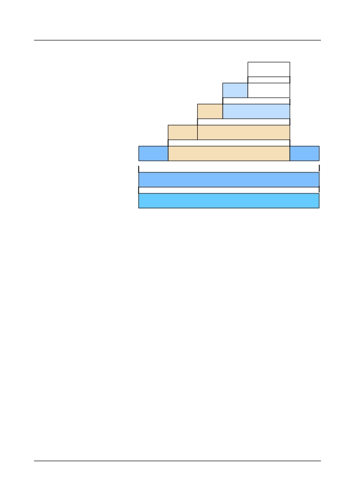
Figure 5-30 OTM-0.m principal containment relationships
Client signal
OPUk
OPUk
OPUk
OH
payload
ODUk
ODUk path
OPUk
PMOH
ODUk
ODUk tandem connection
ODUkP
TCMOH
OTUk[V]
OTUk[V]
OTUk[V] section
ODUkT
OH
FEC
Ochr
Och payload
OTM-0.m
OPS0
OPUk OH: OPUk overhead
ODUk PMOH: ODUk PM overhead
ODUk TCMOH: ODUk TCM overhead
OTUkV OH: OTUkV overhead
OTUk OH: OTUk overhead
- OTM-nr.m: consists of up to n multiplexed optical channels. Figure 5-31 shows the
principal containment relationships of the OTM-nr.m.
132
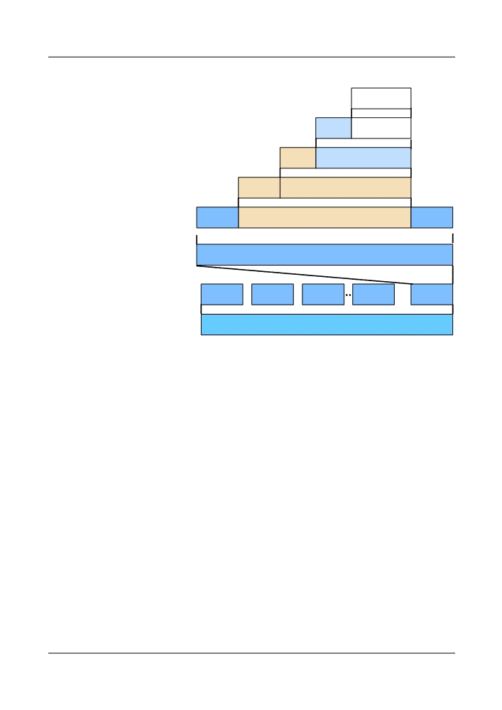
Figure 5-31 OTM-nr.m principal containment relationships
Client signal
OPUk
OPUk
OPUk
OH
payload
ODUk
ODUk path
OPUk
PMOH
ODUk
ODUk tandem connection
ODUkP
TCMOH
OTUk[V]
OTUk[V]
OTUk[V] section
ODUkT
OH
FEC
Ochr
Och payload
OCG-nr.m
OCCp
OCCp
OCCp
OCCp
OCCp
OTM-nr.m
OPSn
OPUk OH: OPUk overhead
ODUk PMOH: ODUk PM overhead
ODUk TCMOH: ODUk TCM overhead
OTUkV OH: OTUkV overhead
OTUk OH: OTUk overhead
OCCo: OCC overhead
5.7.2 OTN Packet Encapsulation
This section describes the mapping paths on the OTN information structure and the OTN signal
transmission mechanism.
OTM Multiplexing and Mapping
Figure 5-32 shows the multiplexing structures and mappings (including wavelength and time
division multiplexing) of various information structures for the OTM of OptiX OSN 8800.
133
Figure 5-32 OTM multiplexing and mapping of OptiX OSN 8800
Client signal
x 1
x 1
ODU3(L)
OPU3(L)
x 16
OTU3[V]
ODTU13
x 1
x 4
ODTU23
ODU3(H)
OPU3(H)
x 1
x 12
X1
ODTUG3
ODTU3.1
x 3
ODTU3.9
OTM-
X1
x 32/ts
0.m
ODTU3.ts
OCCr
Ochr
x 4
Xi
ODTU13
1≤i+j+k≤n
ODTUG3
X1
ODTU23
OTM-
OCG-
Xj
OCCr
Ochr
X1
nr.m
nr.m
X1
Xk
OCCr
Ochr
Client signal
X1
ODU2e(L)x 1
OPU2e(L)
x 1
x 1
OTU2[V]
ODU2(L)
OPU2(L)
x 4
Client signal
X1
x 1
ODTU12
x 1
x 8
X1
ODU2(H)
OPU2(H)
ODTU2.1
Och
ODTUG2
OCC
x 8/ts
X1
x 1
ODTU2.ts
Xi
X1
1≤i+j+k≤n
Xj
OCC
Och
x 4
ODTUG2
ODTU12
OTM-
OCG-
X1
n.m
n.m
Xk
X1
OCC
Och
x 1
ODU1(L)
x 1
Client signal
OTU1[V]
OPU1(L)
X1
X1
x 1
x 2
x 1
ODU1(H)
ODTUG1
ODTU01
OSC
OOS
OPU1(H)
OTS, OMS, OCh, COMMS overhead
x 1
x 1
Client signal
ODU0(L)
OPU0(L)
x 1
x 1
Client signal
ODUflex(L)
OPUflex(L)
ODTUG: Optical channel Data Tributary Unit Group
OCC: Optical channel carrier
OChr: Optical channel with reduced functionality
OCCr: Optical channel carrier with reduced
OCh: Optical channel with full functionality
functionality
OCG: Optical Carrier Group
OSC: Optical supervisory channel
OOS: OTM overhead signal
OTN Types and Bit Rates
Table 5-12 lists the types and bit rates of the OTU.
Table 5-12 OTU types and bit rates
OTU type
OTU nominal bit rate
OTU bit rate tolerance
OTU1
255/238 × 2 488 320 kbit/s
±20 ppm
OTU2
255/237 × 9 953 280 kbit/s
±20 ppm
OTU3
255/236 × 39 813 120 kbit/s
±20 ppm
NOTE
The nominal OTUk rates are approximately: 2 666 057.143 kbit/s (OTU1), 10 709 225.316 kbit/s
(OTU2) and 43 018 413.559 kbit/s (OTU3).
134

NOTE
In Table 5-12, each OTUk consists of 4080*4 bytes. Each OPUk payload consists of 3808*4 bytes. The
255/238, 255/237, and 255/236 of the OTUk nominal rates indicate the ratio of the bytes after the FEC
check to the bytes before the FEC check. The supplementary description is as follows:
l OTU1: The ratio of the bytes after the FEC check to the bytes before the FEC check is as follows:
(4080*4)/(3808*4) = 255/238.
l OTU2: 16 columns of stuffing information are added when the STM-64 is mapped to the OPU2 as
payload. Therefore, the ratio of the bytes after the FEC check to the bytes before the FEC check is as
follows: (4080*4)/[(3808-16)*4] = 255/237.
l OTU3: 32 columns of stuffing information are added when the STM-256 is mapped to the OPU3 as
payload. Therefore, the ratio of the bytes after the FEC check to the bytes before the FEC check is as
follows: (4080*4)/[(3808-32)*4] = 255/236.
Table 5-13 lists the types and bit rates of the ODU.
Table 5-13 ODU types and bit rates
ODU type
ODU nominal bit rate
ODU bit rate tolerance
ODU0
1 244 160 kbit/s
±20 ppm
ODU1
239/238 × 2 488 320 kbit/s
±20 ppm
ODU2
239/237 × 9 953 280 kbit/s
±20 ppm
ODU3
239/236 × 39 813 120 kbit/s
±20 ppm
ODUflex for
239/238 × client signal bit rate
client signal bit rate tolerance, with a
CBR client
maximum of ±100 ppm
signals
NOTE
The nominal ODUk rates are approximately: 2 498 775.126 kbit/s (ODU1), 10 037 273.924 kbit/s
(ODU2) and 40 319 218.983 kbit/s (ODU3).
NOTE
The value "n" represents the number of tributary slots occupied by the ODUflex(GFP). .
NOTE
In Table 5-13, each ODUk consists of 3824*4 bytes. Each OPUk payload consists of 3808*4 bytes. The
239/238, 239/237, and 239/236 of the ODUk nominal rates indicate the ratio of the ODUk bytes to the
OPUk payload excluding the stuffing information. The supplementary description is as follows:
l ODU1: No stuffing information is added when the STM-16 is mapped to the OPU1 as payload.
Therefore, the ratio of the ODU1 bytes to the OPU1 payload is as follows: (3824*4)/(3808*4) =
239/238.
l ODU2: 16 columns of stuffing information are added when the STM-64 is mapped to the OPU2 as
payload. Therefore, the ratio of the ODU2 bytes to the OPU2 payload excluding the stuffing information
is as follows: (3824*4)/[(3808-16)*4] = 239/237.
l ODU3: 32 columns of stuffing information are added when the STM-256 is mapped to the OPU3 as
payload. Therefore, the ratio of the ODU3 bytes to the OPU3 payload excluding the stuffing information
is as follows: (3824*4)/[(3808-32)*4] = 239/236.
Table 5-14 lists the types and bit rates of the OPU.
135