HUAWEI OptiX OSN 8800 T64/T32 Intelligent Optical Transport Platform. Product Description - part 11
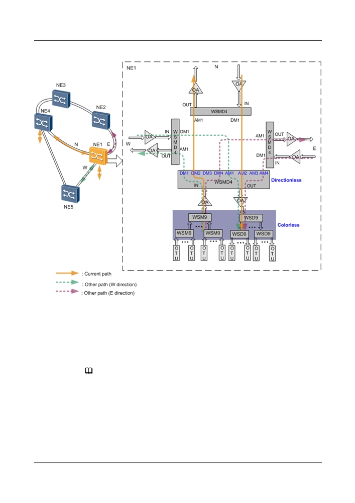
Figure 5-8 Colorless & directionless scenario of the 3-degree ROADM application
5.2.6 4-Degree ROADM
On a 4-degree ROADM network, services can be transmitted in four directions. To smoothly
upgrade a network to one with over four degrees, configure RDU9+WSM9, WSD9+WSM9, or
WSMD9.
NOTE
The WSMD4 in the figure below can be replaced with the RDU9+WSM9, WSD9+WSM9 , or WSMD9.
Colored & Directioned Scenario
Local services are added to the WSMD4 board through the AM1 port and then transmitted to
the south through the OUT port. Services from the west, east, and north pass through the AM2,
AM3, and AM4 ports on the WSMD4 board, heading for the south.
In this scenario, to cross-connect services on NE1 in directions west, north, east, and south, four
groups of M40+D40 must be configured, so each group corresponds to one direction.
103
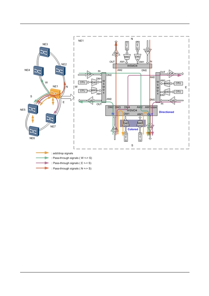
Figure 5-9 Colored & directioned scenario of the 4-degree ROADM application
Colored & Directionless Scenario
Services on NE1 can be transmitted along paths in direction west, north, east, or south.
l To adjust the current path (for example, when services are adjusted or the protection path
is used in case of a faulty working path), manually configure optical cross-connections to
achieve flexible service grooming.
l On an ASON network, the rerouting function automatically finds a path and automatically
creates an optical cross-connection to ensure correct service transmission on NE1. In the
colored scenario, only the same wavelength can be used for service rerouting.
In this scenario, to cross-connect local services on NE1 in direction west, north, east, or south,
only one group of M40+D40 is required.
104
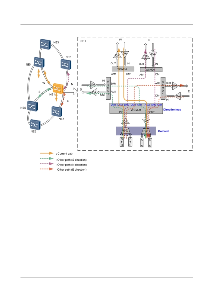
Figure 5-10 Colored & directionless scenario of the 4-degree ROADM application
Colorless & Directionless Scenario
Services on NE1 can be transmitted along paths in direction west, north, east, or south.
l To adjust the current path (for example, when services are adjusted or the protection path
is used in case of a faulty working path), manually configure optical cross-connections to
achieve flexible service grooming.
l On an ASON network, the rerouting function automatically finds a path and automatically
creates an optical cross-connection to ensure correct service transmission on NE1. If a
wavelength-tunable OTU or line board is used in the colorless scenario, service
wavelengths can be flexibly converted during rerouting to avoid a wavelength congestion.
105
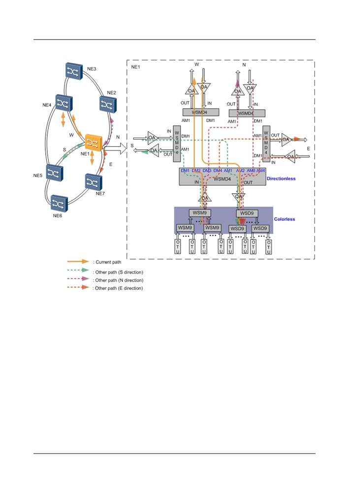
Figure 5-11 Colorless & directionless scenario of the 4-degree ROADM application
5.2.7 9-Degree ROADM
On a 9-degree ROADM network, services can be transmitted in nine directions. Each node must
use RDU9+WSM9 boards, WSD9+WSM9 boards, or WSMD9 boards
Colored & Directionless Scenario
Services on NE1 can be transmitted along paths in nine directions.
l To adjust the current path (for example, when services are adjusted or the protection path
is used in case of a faulty working path), manually configure optical cross-connections to
achieve flexible service grooming.
l On an ASON network, the rerouting function automatically finds a path and automatically
creates an optical cross-connection to ensure correct service transmission on NE1. In the
colored scenario, only the same wavelength can be used for service rerouting.
In this scenario, to cross-connect local services on NE1 in direction 1 to direction 9, only one
group of M40+D40 is required.
106
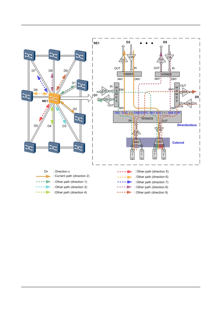
Figure 5-12 Colored & directionless scenario of the 9-degree ROADM application
Colorless & Directionless Scenario
Services on NE1 can be transmitted along paths in nine directions.
l To adjust the current path (for example, when services are adjusted or the protection path
is used in case of a faulty working path), manually configure optical cross-connections to
achieve flexible service grooming.
l On an ASON network, the rerouting function automatically finds a path and automatically
creates an optical cross-connection to ensure correct service transmission on NE1. If a
wavelength-tunable OTU or line board is used in the colorless scenario, service
wavelengths can be flexibly converted during rerouting to avoid a wavelength congestion.
107
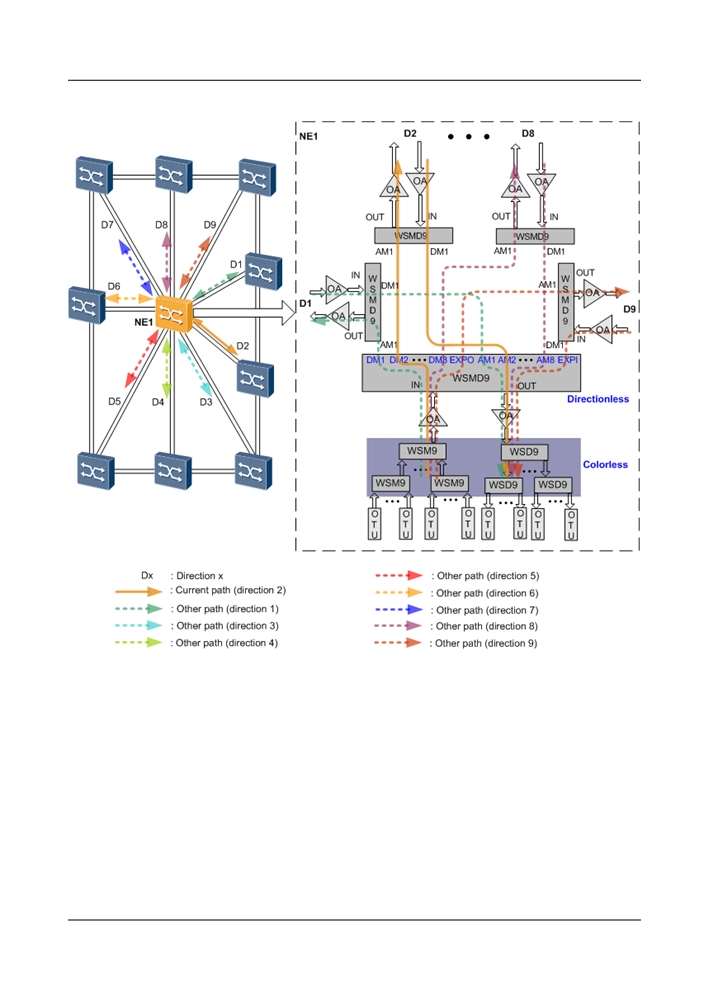
Figure 5-13 Colorless & directionless scenario of the 9-degree ROADM application
5.3 Transmission System
5.3.1 Integrated System and Open System Compatibility
The OptiX OSN 8800 can realize the compatibility of the integrated and open DWDM systems.
The open DWDM system is configured with OTUs to convert non-standard wavelengths into
ITU-T G.694.1-compliant wavelengths.
The integrated DWDM system does not need OTUs when its client-side equipment (for example,
the SDH equipment) has optical transmitter interfaces that comply with ITU-T G.694.1.
108
l In the integrated DWDM system, if the optical specifications of the accessed signals of the
client equipment comply with the system specifications for the OptiX OSN 8800, the VOA
board, the MUX board with the built-in EVOA, or the ROADM board can be used to
equalize the optical power of the accessed signals.
l In the integrated DWDM system, the dispersion tolerance of the accessed signals of the
client equipment should not be smaller than the dispersion tolerance of the OTU board used
in the OptiX OSN 8800 to meet the requirement of the system dispersion compensation for
the transmission fiber.
l The integrated DWDM system is not recommended in view of factors such as equipment
operation, maintenance, and fault locating.
5.3.2 40 Gbit/s
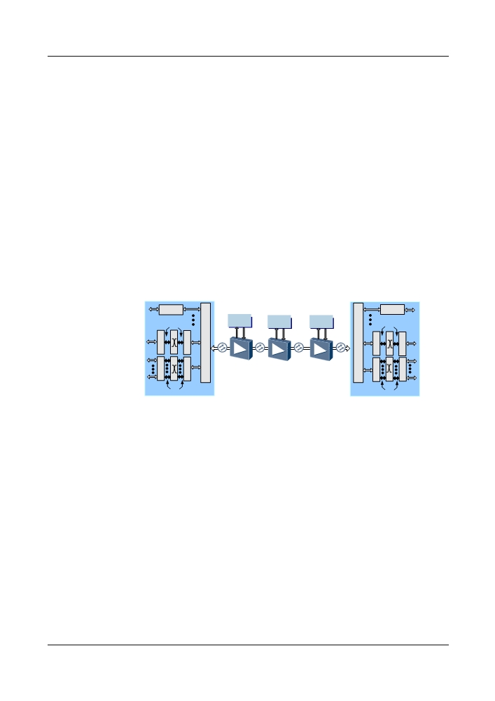
The OptiX OSN 8800 provides a 40/80 x 40 Gbit/s transmission solution.
l
40 Gbit/s non-coherent transmission solution
Figure 5-14 shows the a typical application of the 40 Gbit/s non-coherent transmission
solution.
Figure 5-14 Typical application of the 40 Gbit/s transmission solution
OTU
40/80x40 Gbit/s
OTU
M
M
DCM
DCM
DCM
ODU3
U
U
ODU3
X
X
Client
Client
/
/
services
T
N
N
T
D
D
services
M
M
U
U
T
N
X
X
N
T
ODU2/ODU1/ODU0
ODU2/ODU1/ODU0
T: Tributary boards
N: Line boards
5.3.3 3.1.5 10 Gbit/s, 40 Gbit/s, 100 Gbit/s Hybrid Transmission
With the emergence of service requirements, the existing 10 Gbit/s WDM transmission system
may be gradually upgraded to the 40 Gbit/s transmission system. When this occurs, the hybrid
transmission of the 40 Gbit/s and 10 Gbit/s signals becomes very important.
The OptiX OSN 8800 supports hybrid transmission of 10 Gbit/s signals, 40 Gbit/s non-coherent
signals, 40 Gbit/s coherent signals, and 100 Gbit/s coherent signals, and any of their
combinations. Thanks to this feature, the incumbent networks can be upgraded to ones with
larger capacity based on proper system designs of system performance parameters, protecting
operators' investments while addressing the increasing bandwidth demands. Figure 5-15 shows
hybrid transmission of 100 Gbit/s, 40 Gbit/s, and 10 Gbit/s signals.
109
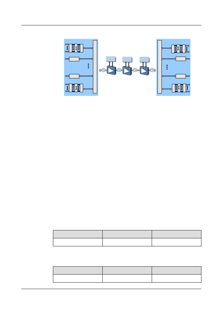
Figure 5-15 Hybrid transmission of 40 Gbit/s and 10 Gbit/s signals in the non-coherent system
10 Gbit/s
10 Gbit/s
T
N
N
T
10 Gbit/s
M
M
10 Gbit/s
U
U
OTU
OTU
DCM
DCM
DCM
X
X
/
/
Client
Client
D
D
services
services
M
M
40 Gbit/s
U
U
40 Gbit/s
OTU
OTU
X
X
40 Gbit/s
40 Gbit/s
T
N
N
T
T: Tributary boards
N: Line boards
5.3.4 Transmission Distance
l For 40 Gbit/s rate in the 40-wavelength system, a maximum of 20 x 22 dB transmission
without electrical regenerator is supported.
l For 40 Gbit/s rate in the 80-wavelength system, a maximum of 18 x 22 dB transmission
without electrical regenerator is supported.
l For 10 Gbit/s rate in the 40-wavelength system, a maximum of 32 x 22 dB transmission
without electrical regenerator is supported.
l For 10 Gbit/s rate in the 80-wavelength system, a maximum of 25 x 22 dB transmission
without electrical regenerator is supported.
l For 2.5 Gbit/s rate, a maximum of 25 x 22 dB transmission without electrical regenerator
is supported.
l For 10 Gbit/s rate system, supports a maximum of 1 x 82 dB single-span ultra long-distance
transmission.
l For the CWDM systems, a maximum of 80 km transmission distance is supported.
Huawei OSN series WDM equipment supports various links or spans based on different
modulation schemes for systems with diversified channel spacing.
Table 5-5 2.5 Gbit/s system span
Channel Spacing
Modulation Scheme
22 dB Span
100 GHz
NRZ
25 x 22 dB
Table 5-6 10 Gbit/s system span
Channel Spacing
Modulation Scheme
22 dB Span
100 GHz
DRZ
32 x 22 dB
110

Channel Spacing
Modulation Scheme
22 dB Span
NRZ
27 x 22 dB
NRZ (XFP)
27 x 22 dB
50 GHz
DRZ
25 x 22 dB
NRZ
22 x 22 dB
NRZ (XFP)
22 x 22 dB
Table 5-7 40 Gbit/s system span
Channel Spacing
Modulation Scheme
22 dB Span
100 GHz
DQPSK
20 x 22 dB
50 GHz
ODB
8 x 22 dB
DQPSK
18 x 22 dB
5.4 Protection
The OptiX OSN 8800 T32/8800 T64 provides various types of equipment-level protection and
network-level protection.
5.4.1 Equipment Level Protection
The OptiX OSN 8800 T32 and OptiX OSN 8800 T64 provide cross-connect board 1+1
protection, SCC board 1+1 protection, STG board 1+1 protection, DC input protection,
redundancy protection for fans and inter-subrack communication protection.
5.4.1.1 Cross-Connect Board 1+1 Protection
The cross-connect board adopts 1+1 backup. It is recommended that active and standby cross-
connect boards be of the same type.
Service boards receive signals and process overheads. Then, the boards transmit the signals to
the active and the standby cross-connect boards. The active and the standby cross-connect boards
send the data after cross-connection to service boards. Service boards select the data from the
cross-connect boards. Configuration of the active cross-connect board is the same as the
configuration of the standby cross-connect board. The two boards are independent of each other.
Forcible switching can be performed between the two cross-connection boards without affecting
the existing services.
The cross matrix of the active cross-connect board is the same the cross matrix of the standby
cross-connect board. When the standby cross-connect board receives information about
abnormal active cross-connect board or when the NM system issues a switching command, the
standby cross-connect board takes over the work from the active cross-connect board, sets itself
to be in working status, and reports a switching event.
111
There are two types of switching for the 1+1 protection switching of cross-connect boards:
l Automatic switching
When the service boards detect the abnormal status of cross-connect boards or buses, a
switching is performed automatically. The switching does not need to be performed
manually.
l Manual switching
When a switching is required in a test during the normal running of the active and the
standby cross-connect boards, the switching can be performed manually.
NOTE
When a switching occurs between the cross-connect boards, a switching also occurs between the active
and standby clock boards.
5.4.1.2 SCC Board 1+1 Protection
The SCC adopts 1+1 backup.
The service boards receive signals and process overheads. Then, the boards transmit the
overheads to both the active and the standby SCCs. The active and the standby SCCs send the
data after overhead processing to service boards. The service boards select the data according
to the status of SCCs. Configuration of the active SCC is the same as the configuration of the
standby SCC. The two boards are independent of each other.
The communication between SCCs and other boards is performed mainly through Ethernet.
When the status is normal, the data on service boards and the standby SCC is from the active
SCC. There is no inter-board communication between the standby SCC and service boards. Only
when the standby SCC is in the working mode, it has inter-board communication with other
boards.
When the active SCC is in normal status, the standby SCC is in backup status. When the standby
SCC receives information about abnormal active SCC or when the NM system issues a switching
command, the standby SCC takes over the work from the active SCC, sets itself to be in working
status, and reports a switching event.
There are two types of switching for the 1+1 protection switching of SCCs:
l Automatic switching
The SCC detects its own status through hardware or software. If it is in the abnormal status,
a switching is performed automatically. The switching is performed by the board and no
manual operation is required.
l Manual switching
When a switching is required in a test during the normal running of the active and the
standby SCCs, the switching can be performed manually.
5.4.1.3 STG Board 1+1 Protection
The clock board STG adopts 1+1 backup. The two STGs serve as mutual backups. When both
of them are normal, one of them functions as the active board, and the other functions as the
standby board. Service boards select the clock source according to the status of the two STGs.
When the active STG is faulty, an active/standby switching occurs. Then, the standby STG
becomes active, and the services boards select the clock from the current active STG according
to the status of the two STGs.
112
Configuration of the active STG is the same as the configuration of the standby STG. The two
boards are independent of each other. When the active clock board is in abnormal state, the
standby clock board automatically takes over the work. Hence, there is no impact on the normal
operation of the equipment.
There are two types of switching for the 1+1 protection switching of STGs:
l Automatic switching
The STG detects its own status through hardware or software. If it is in the abnormal status,
a switching is performed automatically. The switching is performed by the board and no
manual operation is required.
l Manual switching
When a switching is required in a test during the normal running of the active and the
standby STGs, the switching can be performed manually.
NOTE
When a switching occurs between the clock boards, a switching also occurs between the active and standby
cross-connect boards.
5.4.1.4 OptiX OSN 8800 T64 DC Input Protection
The power supply system of an OptiX OSN 8800 T64 subrack uses eight power supply boards
to separately provide -48 V/-60V power inputs for the four sections of the subrack.
The power supply system supports eight -48 V/-60 V DC power inputs for mutual backup in
OptiX OSN 8800 T64 subrack. The subrack adopts switched-mode power supply scheme for
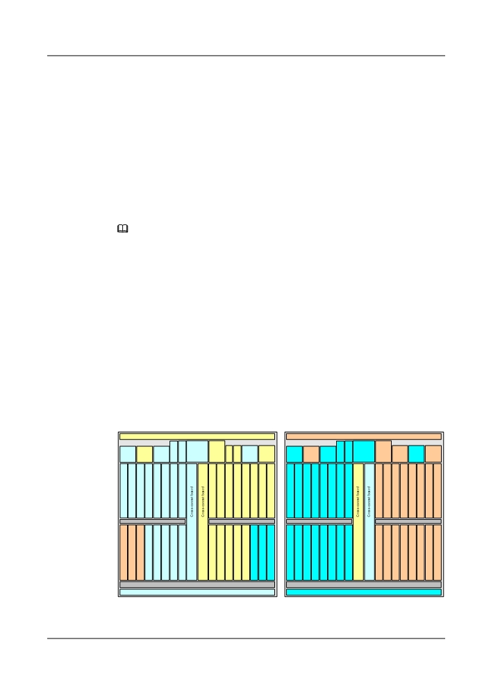
four areas which are shown in Figure 5-16. The area has the same color is defined as one area.
Each area is configured with a pair of power supplies in mutual backup (IU69 and IU78, IU70
and IU79, IU80 and IU88, and IU81 and IU89). The normal operation of the equipment is not
affected in the case of failure of any external input -48 V/-60 V power supply. Figure 5-16 shows
the four pairs of power supplies of mutual backup.
Figure 5-16 Power distribution and supply for the general 8800 T64 subrack
Front
Rear
IU91
IU93
A
A
U
SCC
STG
U
SCC
STG
PIU
PIU
EFI2
X
IU
EF
IU
PIU
PIU
PIU
PIU
STI
X
IU
ATE
PIU
PIU
IU69
IU70
IU71
IU
73
IU74
IU75
I1IU
77
IU78
IU79
IU80
IU81
IU82
IU
84
IU85
IU86
IU87
IU88
IU89
72
76
83
IU
IU
IU
IU
IU
IU
IU
IU
IU
IU
IU
IU
IU
IU
IU
IU
IU
IU
IU
IU
IU
IU
IU
IU
IU
IU
IU
IU
IU
IU
IU
IU
19
20
21
22
23
24
25
26
27
28
29
30
31
32
33
34
53
54
55
56
57
58
59
60
61
62
63
64
65
66
67
68
IU
IU
IU
IU
9
10
43
44
IU
IU
IU
IU
IU
IU
IU
IU
IU
IU
IU
IU
IU
IU
IU
IU
IU
IU
IU
IU
IU
IU
IU
IU
IU
IU
IU
IU
IU
IU
IU
IU
1
2
3
4
5
6
7
8
11
12
13
14
15
16
17
18
35
36
37
38
39
40
41
42
45
46
47
48
49
50
51
52
IU90
IU92
113