HUAWEI OptiX OSN 8800 T64/T32 Intelligent Optical Transport Platform. Product Description - part 9
The functions of the fixed optical add/drop multiplexer unit are as follows:
l TN11CMR2: Adds/drops and multiplexes two signals to/from the multiplexed signals.
l TN11CMR4: Adds/drops and multiplexes four signals to/from the multiplexed signals.
l TN11DMR1: Adds/drops and multiplexes one channel of 1310 nm wavelength in east
direction and one in west direction.
l TN11MR2: Adds/drops and multiplexes two signals to/from the multiplexed signals.
l TN11MR4: Adds/drops and multiplexes four signals to/from the multiplexed signals.
l TN11MR8: Adds/drops and multiplexes eight signals to/from the multiplexed signals.
l TN11MR8V: Adds/Drops and multiplexes eight signals to/from the multiplexed signals.
Adjusts the multiplexed input optical power of WDM-side signal and the input optical
power of cascade ports for pass-through wavelengths.
l TN11SBM2: Adds/drops two wavelengths to/from the multiplexed signals and multiplexes
the other two wavelengths into the multiplexed signals. The optical signals that are added
or dropped, and the optical signals that are multiplexed must belong to different
wavelengths. The TN11SBM2 unit is applied to single-fiber bidirectional system.
4.2.4.10 Reconfigurable Optical Add/Drop Multiplexing unit
The reconfigurable optical add and drop multiplexing unit demultiplexes any single-wavelength
signal from multiplexed signals and sends it to the OTU. It also multiplexes any single-
wavelength signal into multiplexed signals. The reconfigurable optical add and drop
multiplexing units include:
l RMU9: 9-port ROADM multiplexing board
l RDU9: 9-port ROADM demultiplexing board
l ROAM: reconfigurable optical adding board
l WSD9: 9-port wavelength selective switching demultiplexing board
l WSM9: 9-port wavelength selective switching multiplexing board
l WSMD2: 2-port wavelength selective switching multiplexing and demultiplexing board
l WSMD4: 4-port wavelength selective switching multiplexing and demultiplexing board
l WSMD9: 9-port wavelength selective switching multiplexing and demultiplexing board
The functions of the reconfigurable optical add and drop multiplexing units are as follows:
l TN11RDU9: Broadcasts the main path signals in nine directions at the same time.
l TN11RMU9: Adds eight single-channel signal or multi-channel signals to the main path.
Used with the OTU with tunable wavelength, the RMU9 realizes the dynamic input of eight
channel signals.
l TN11ROAM: Realizes the dynamic adding/dropping, pass-through, and blocking of a
maximum of 40 wavelengths as well as the dynamic grooming of wavelengths for the
services on the ring network. The board does not support the access of colorless signals.
l TN12WSD9/TN13WSD9: Achieves the dynamic and configurable demultiplexing of any
wavelengths to any ports. A node on the ring or chain network can transmit any wavelength
combination to any ports so as to achieve the dynamic allocation of wavelengths. The
TN12WSD9 unit is used in the 40-wavelength system and the TN13WSD9 unit is used in
the 80-wavelength system. The board can also add eight channels of colorless signals to
the main path, and supports board cascade for adding more channels of signals.
81
l
TN12WSM9/TN13WSM9: Achieves the dynamic and configurable multiplexing of any
wavelengths to any ports. A node on the ring or chain network can receive any wavelengths
at the local station through any ports as to achieve the dynamic allocation of wavelengths.
The TN12WSM9 unit is used in the 40-wavelength system and the TN13WSM9 unit is
used in the 80-wavelength system. The board can also add eight channels of colorless
signals to the main path, and supports board cascade for adding more channels of signals.
l
TN11WSMD2: Achieves service broadcasting function, and supports the function of
configurable multiplexing any wavelengths. Any node on a ring or chain network can
broadcast the signals received from the main optical path as two channels of the same
signals, and can input any wavelengths added locally to the AM port. The TN11WSMD2
unit is used in the 40-wavelength system.
l
TN11WSMD4/TN12WSMD4: Achieves service broadcasting function, and supports the
function of configurable multiplexing any wavelengths. Any node on a ring or chain
network can broadcast the signals received from the main optical path as four channels of
the same signals, and can input any wavelengths added locally to any port. The
TN11WSMD4 unit is used in the 40-wavelength system and the TN12WSMD4 unit is used
in the 80-wavelength system.
l
TN11WSMD9: Achieves service broadcasting function, and supports the function of
configurable multiplexing any wavelengths. Any node on a ring or chain network can
broadcast the signals received from the main optical path as nine channels of the same
signals, and can input any wavelengths added locally to any port. The TN11WSMD9 unit
is used in the 80-wavelength system.
4.2.4.11 Optical Amplifier Board
The optical amplifier board amplifies the power of the multiplexed optical signals to extend the
transmission distance.
The optical amplifier boards include:
l CRPC: case-shaped Raman pump amplifier unit for C-band
l OAU1: optical amplifier unit
l OBU1: optical booster unit
l OBU2: optical booster unit
l HBA: high-power booster amplifier board
l DAS1: double optical amplifier unit with supervisory channel
NOTE
OAU1 uses two amplifiers to provide two-level amplification and a DCM module can be configured
between the two amplifiers. An OAU1 board provides two pump sources with pump wavelengths of 980
nm and 1480 nm. OBU1 or OBU2 adopts one-level amplification and provides only one pump source with
a pump wavelength of 980 nm.
The functions of the optical amplifier units are as follows:
l TN11CRPC: Generates multi-channel pump light of high power, providing energy for the
amplification of signals in the fiber. Realizes the distributed in-service amplification of
signals over long distance with wide bandwidth and low noise. It includes two types:
- CRPC01: Adopts backward pumping technology. The typical gain is 10 dB for G.652
fiber. The typical gain is 12 dB for LEAF fiber.
- CRPC03: Adopts forward pumping technology. The typical gain is 10 dB for G.652
fiber.
82
l
TN11OAU1: Amplifies the input optical signals in C band. The total wavelengths range
from 1529 nm to 1561 nm. It includes four types:
- OAU101: The OAU101 continuously adjusts the gain from 20 dB to 31 dB based on
the input optical power.
- OAU102: The OAU102 continuously adjusts the gain from 20 dB to 31 dB based on
the input optical power.
- OAU103: The OAU103 continuously adjusts the gain from 24 dB to 36 dB based on
the input optical power.
- OAU105: The OAU105 continuously adjusts the gain from 23 dB to 34 dB based on
the input optical power.
l
TN12OAU1: Adjusts the optical power of the input optical signals, and amplifies the input
optical signals in C band. The total wavelengths range from 1529 nm to 1561 nm. It includes
five types:
- OAU100: The OAU100 continuously adjusts the gain from 16 dB to 25.5 dB based on
the input optical power.
- OAU101: The OAU101 continuously adjusts the gain from 20 dB to 31 dB based on
the input optical power.
- OAU102: The OAU102 continuously adjusts the gain from 20 dB to 31 dB.
- OAU103: The OAU103 continuously adjusts the gain from 24 dB to 36 dB based on
the input optical power.
- OAU105: The OAU105 continuously adjusts the gain from 23 dB to 34 dB based on
the input optical power.
l
TN13OAU1: Adjusts the optical power of the input optical signals, and amplifies the input
optical signals in C band. The total wavelengths range from 1529 nm to 1561 nm. It includes
three types:
- OAU101: The OAU101 continuously adjusts the gain from 20 dB to 31 dB based on
the input optical power.
- OAU103: The OAU103 continuously adjusts the gain from 24 dB to 36 dB based on
the input optical power.
- OAU105: The OAU105 continuously adjusts the gain from 23 dB to 34 dB based on
the input optical power.
l
TN11OBU1: Amplifies the input optical signals in C band. The total wavelengths range
from 1529 nm to 1561 nm. It includes three types:
- OBU101: The typical gain is 20 dB.
- OBU103: The typical gain is 23 dB.
- OBU104: The typical gain is 17 dB.
l
TN12OBU1: Adjusts the optical power of the input optical signals, and amplifies the input
optical signals in C band. The total wavelengths range from 1529 nm to 1561 nm. It includes
four types:
- OBU101: The typical gain is 20 dB.
- OBU103: The typical gain is 23 dB.
- OBU104: The typical gain is 17 dB.
- OBU1P1: Configured at the receive site, is an OA board intended for PID and is used
together with the TN55NPO2/TN55NPO2E board.
83
l TN11OBU2: Amplifies the input optical signals in C band. The total wavelengths range
from 1529 nm to 1561 nm. It includes one type OBU205 and the typical gain is 23 dB.
l TN12OBU2: Adjusts the optical power of the input optical signals, and amplifies the input
optical signals in C band. The total wavelengths range from 1529 nm to 1561 nm. It includes
one type OBU205 and the typical gain is 23 dB.
l TN11HBA: Amplifies the input optical signals in C band. The total wavelengths range
from 1529 nm to 1561 nm. This ensures the high output optical power of the board. The
board mainly amplifies the launched optical power to meet the requirement of ultra-long
haul transmission. The typical gain is 29 dB.
l TN11DAS1: Integrates the functions of the OAU101, FIU, and SC1 boards.
- Amplifies the input optical signals in C band with the wavelength range of 1529 nm to
1561 nm. The board can continuously adjust the gain from 20 dB to 31 dB.
- Multiplexes or demultiplexes signals on the optical supervisory channel into or from
on the main optical path.
- Receives, transmits, controls, and processes one channel of signals on the optical
supervisory channel. The operating wavelength of the optical supervisory channel
ranges from 1480 nm to 1520 nm.
4.2.4.12 Optical Supervisory Channel Board
The OSC unit transmits and extracts the system overhead information and then sends it to the
SCC after simple processing.
The OSC units include:
l SC1: unidirectional optical supervisory channel unit
l SC2: bidirectional optical supervisory channel unit
l HSC1: high power unidirectional optical supervisory channel unit
l ST2: bidirectional optical supervisory channel and timing transmission unit
The functions of the OSC units are as follows:
l TN12SC1: The SC1 is used to receive, process, and transmit one optical supervisory signal.
The SC1 supports a maximum of 48 dB transmission.
l TN12SC2: The SC2 is used to receive, process, and transmit two optical supervisory
signals. The SC2 supports a maximum of 48 dB transmission.
l TN11HSC1: The HSC1 is used to receive, process, and transmit one optical supervisory
signal. The HSC1 supports a maximum of 53 dB transmission.
l TN11ST2: The ST2 is used to receive, process, and transmit two optical supervisory signals.
- The ST2 board supports transparent transmission of two channels of FE electrical
signals
- The ST2 board supports transparent transmission of two channels of 2M clock signals.
- The ST2 board supports control of the DCN communication flow.
- The ST2 board supports forward error correction (FEC).
- The ST2 board supports IEEE 1588 v2 function.
4.2.4.13 Optical Protection Board
The optical protection unit protects the network system in self-healing mode.
84
The optical protection units include:
l OLP: optical line protection unit
l DCP: 2-channel optical path protection unit
l SCS: sync optical channel separator unit
The functions of the optical protection units are as follows:
l TN11OLP/TN12OLP:
- Provides optical line protection. When the active fiber decreases in performance, it
automatically switches to the standby fiber.
- Provides intra-board 1+1 protection to protect the services of the OTU that has no dual
fed and selective receiving function.
- Provides client 1+1 protection, which uses a working OTU and a protection OTU to
protect the client-side services.
- TN11OLP supports multi-mode optical module.
l TN11DCP/TN12DCP:
- Provides intra-board 1+1 protection to protect the services of the OTU that has no dual
fed and selective receiving function. Compared with the OLP, the DCP provides
protection for two signals so as to realize high-integrated 1+1 protection.
- Provides client 1+1 protection, which uses a working OTU and a protection OTU to
protect the client-side services.
- Provides OWSP protection by occupying two wavelengths to protect one channel of
service at two adjacent stations.
l TN11SCS:
- Provides client 1+1 protection, which uses a working OTU and a protection OTU to
protect the client-side services.
4.2.4.14 Interface Board
The interface boards provide functional interfaces such as management interface, inter-subrack
communication interface, alarm output and cascading interface, alarm input and output interface.
ATE
On the OptiX OSN 8800, the /TN51ATE board provides the following interfaces:
l Interface for eight alarm outputs and cascading.
l Interface for eight alarm inputs.
EFI
On the OptiX OSN 8800, the TN51EFI1 and TN51EFI2 boards provide the following interfaces:
TN51EFI1
l Network management interface:
- Connects the network interface on the NEs through a network cable to that on the NMS
server to achieve the management of the NMS over the NEs.
85
- Connects the NM_ETH1/NM_ETH2 network interface on one NE through a network
cable to that on another NE to achieve communication between NEs.
l OAM interface: The OAM interface is a serial NM interface, providing functions of serial
NM and supporting X.25 protocol.
TN51EFI2
l Alarm output/concatenation interface: This interface drives the running indicators and
alarm indicators of the cabinet that holds the subrack.
l Network management interface:
- Connects the network interface on the NEs through a network cable to that on the NMS
server to achieve the management of the NMS over the NEs.
- Connects the NM_ETH1/NM_ETH2 network interface on one NE through a network
cable to that on another NE to achieve communication between NEs.
l Subrack communication interface:
- Connects a network cable from the ETH1/ETH2/ETH3 interface on one subrack to
corresponding interfaces on the other subracks to achieve the communication between
the master subrack and slave subracks.
NOTE
When inter-subrack protection is configured, the ETH3 interface cannot be used for the
communication between the master and slave subracks.
- Connects a network cable to a CRPC or ROP board to achieve communication with the
CRPC or ROP board.
STI
On the OptiX OSN 8800 T32 and OptiX OSN 8800 T64, the TN52STI and TNL1STI boards
are the user interface boards for the STG board. The STI board provides the following interfaces:
l Interface for inputting and outputting clock signals.
l Interface for inputting and outputting time signals.
l Orderwire interface.
l F1 interface.
NOTE
The orderwire interface and F1 interface are available only on the TNL1STI board.
4.2.4.15 Spectrum Analyzer Board
The spectrum analyzer units include:
l MCA4: 4-channel spectrum analyzer unit
l MCA8: 8-channel spectrum analyzer unit
l WMU: wavelength monitor unit
l OPM8: 8-channel optical power monitoring board
The functions of the spectrum analyzer units are as follows:
l TN11MCA4: Monitors in service the
- Central wavelength
- Power value
86
- Signal-to-noise ratio
- The number of optical wavelengths of the optical signal
The information monitored is reported to the SCC for processing. Provides the spectral
analysis for four channels.
l
TN11MCA8: Monitors in service the
- Central wavelength
- Power value
- Signal-to-noise ratio
- The number of optical wavelengths of the optical signal
The information monitored is reported to the SCC for processing. Provides the spectral
analysis for eight channels.
l
TN11WMU: Performs centralized detection to the OTU board at the transmit end of the
system in terms of the wavelength precision. The WMU board reports the wavelength
deviation to the SCC.
l
TN11OPM8: Monitors in service the
- Power value
- The number of optical wavelengths of the optical signal
The information monitored is reported to the SCC for processing. Provides the spectral
analysis for four channels.
4.2.4.16 Variable Optical Attenuator Board
The variable optical attenuator units include:
l VA1: 1-channel variable optical attenuator unit
l VA4: 4-channel variable optical attenuator unit
The functions of the variable optical attenuator units are as followed:
l TN12VA1: Adjusts the optical power of one optical channel according to the control
command sent by the SCC.
l TN12VA4: Adjusts the optical power of four optical channels according to the control
command sent by the SCC.
4.2.4.17 Optical Power and Dispersion Equalizing Board
The optical power and dispersion slope equalizing unit is used to adjust the optical power and
dispersion and includes:
l DCU: dispersion compensation unit
l GFU: gain flatness unit
l TDC: single-channel tunable-dispersion compensation board
The functions of the optical power and dispersion equalizing units are as followed:
l TN11DCU: The DCU board compensates for the dispersion which is accumulated in the
fiber during transmission and compresses optical signal pulse. In this way, the optical
signals transmitted can be restored at the output end. In addition, when used together with
an amplifier board, the DCU board can realize long haul optical transmission.
87
l TN11GFU: Applies to the scenario where the Raman amplifier is used. Uses the gain
flattening filter (GFF) for static compensation on uneven gains caused by optical Raman
amplifier concatenation.
l TN11TDC: The TDC is used for C-band optical signals. Compensates for the dispersion
in the single channel. The dispersion is adjustable.
4.2.5 Small Form-Factor Pluggable (SFP) Module
There are four types of pluggable optical modules: the enhanced small form-factor pluggable
(eSFP), the small form-factor pluggable plus (SFP+), the tunable 10 Gbit/s small form-factor
pluggable (TXFP) and the 10 Gbit/s small form-factor pluggable (XFP). Because they are
pluggable, when you need to adjust the type of accessed services or replace a faulty optical
module, you can directly replace it without replacing its dominant board.
4.3 Software Architecture
The system software includes the board software, NE software and the network management
system.
4.3.1 Overview
The system software is of a modular design. Each module provides specific functions and works
with the other modules.
The entire software is distributed in three modules including board software, NE software and
NM system.
The system software is designed with a hierarchical structure. Each layer performs specific
functions and provides service for the upper layer.
The system software architecture is shown in Figure 4-27.
In the diagram, all the modules are NE software except the "Network Management System" and
"Board Software" modules.
88
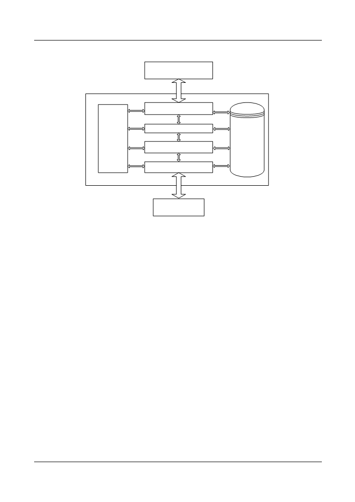
Figure 4-27 Software architecture
Network Management
System
High Level
Communication Module
Real-time
Network side Module
multi-task
Database
operating
Management
Equipment Management
system
Module
Module
Communication Module
NE software
Board Software
4.3.2 Communication Protocols and Interfaces
The Qx interface is used for communication. Complete protocol stack and messages of the Qx
interface are described in ITU-T G.773, Q.811 and Q.812.
The Qx interface is mainly used to connect the mediation device (MD), Q adaptation (QA) and
NE (NE) equipment with the operating system (OS) through local communication network
(LCN).
At present, QA is provided by the NE management layer. MD and OS are provided by the NM
layer. They are connected to each other through the Qx interface.
According to the Recommendations, the Qx interface provided by the system is developed on
the basis of TCP/IP connectionless network layer service (CLNS1) protocol stack.
In addition, to support remote access of the NM through Modem, the IP layer uses serial line
internet protocol (SLIP).
89
5
Functions and Features
About This Chapter
5.1 Electrical Layer Grooming
The OptiX OSN 8800 T64/8800 T32 supports the integrated grooming of electrical layer signals.
5.2 Optical Layer Grooming
5.3 Transmission System
5.4 Protection
The OptiX OSN 8800 T32/8800 T64 provides various types of equipment-level protection and
network-level protection.
5.5 Data Characteristics
The OptiX OSN 8800 T32/8800 T64 supports the Ethernet features and mainly supports the
following Ethernet services: EPL, EVPL (QinQ), and EPLAN.
5.6 Optical Power Management
The optical power management includes IPA, IPA of Raman System, IPA of PID, ALC, APE
, EAPE, OPA and AGC.
5.7 OTN Technologies
OTN technologies cover electrical-layer access, optical-layer access, mapping, multiplexing,
cross-connection, and protection.
5.8 WDM Technologies
This chapter describes the WDM technologies and functions implemented on the OptiX OSN
8800 T32/8800 T64.
5.9 Clock Synchronization Solutions
This section describes the clock synchronization solutions used by the OptiX OSN 8800in
different scenarios.
5.10 ASON Management
An automatically switched optical network (ASON) is a new-generation optical transmission
network.
5.11 Transmission of Network Management Information
There are three communication modes: HWECC, OSI over DCC, IP over DCC.
90
5.12 Network Management Tools and Protocols
The NM system manages alarm, performance, configuration, communication, security, and
topology of the entire optical transmission system.
5.13 License Control
When creating the NE or the slave subrack on the U2000, you need to configure license. The
U2000 distributes the license files to the corresponding NEs. In this manner, the management
of service capacity and service types is realized.
5.14 Features of Upgrade and Maintenance
91