HUAWEI OptiX OSN 8800 T64/T32 Intelligent Optical Transport Platform. Product Description - part 8
Board
Function
TN55TQX
TN55TQX convert signal as follows:
l 4 x FC800/FC1200/10GE LAN/10GE WAN/
STM-64/OC-192/OTU2/OTU2e <-> 4 x ODU2/
ODU2e
l 4 x FC800 <-> 4 x ODUflex
TN53TSXL
TN53TSXL convert signal as follows:
l 1 x STM-256/OC-768/OTU3 <-> 1 x ODU3
4.2.4.4 Line Board
The line unit includes:
NS2: 10G line service processing board
ND2: 2 x 10G line service processing board
NQ2: 4 x 10G line service processing board
NS3: 40G line service processing board
Table 4-26 shows the functions of the line board.
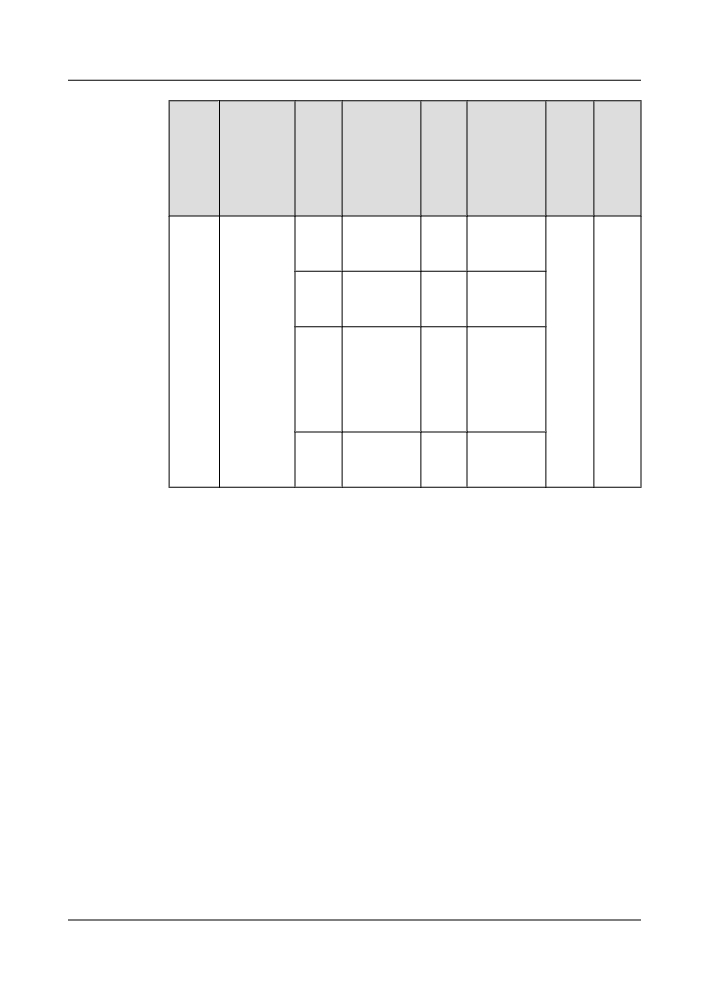
Table 4-26 Functions of the line unit
Board
Board
Num
Type of
Num
Type of
Hybri
Rege
Descriptio
ber of
Signals on
ber of
Signals on
d
nerat
n
Back
Backplane
WD
WDM Side
Trans
or
plane
Side
M
missi
Funct
Side
Side
on
ion
Signa
Signa
ls
ls
TN52
10G line
8
ODUO
1
OTU2
Suppo
Not
NS2
service
Electrical
Optical
rts
suppor
processing
signal
signal
hybrid
ted
board
transm
4
ODU1
1
OTU2
ission
Electrical
Optical
of
signal
signal
ODU0
and
1
l ODU2
1
l OTU2
ODU1
Electrical
Optical
signals
signal
signal
l ODU2e
l OTU2e
Electrical
Optical
signal
signal
70
Board
Board
Num
Type of
Num
Type of
Hybri
Rege
Descriptio
ber of
Signals on
ber of
Signals on
d
nerat
n
Back
Backplane
WD
WDM Side
Trans
or
plane
Side
M
missi
Funct
Side
Side
on
ion
Signa
Signa
ls
ls
TN53
10G line
8
ODUO
1
OTU2
Suppo
Not
NS2
service
Electrical
Optical
rts
suppor
processing
signal
signal
hybrid
ted
board
transm
4
ODU1
1
OTU2
ission
Electrical
Optical
of
signal
signal
ODUfl
ex,
1
l ODU2
1
l OTU2
ODU0
Electrical
Optical
, and
signal
signal
ODU1
l ODU2e
l OTU2e
signals
Electrical
Optical
signal
signal
1
ODUflex
1
OTU2
Electrical
Optical
signal
signal
TN52
2 x 10G line
16
ODU0
2
OTU2
Suppo
Suppo
ND2
service
Electrical
Optical
rts
rted
processing
signal
signal
hybrid
board
transm
8
ODU1
2
OTU2
ission
Electrical
Optical
of
signal
signal
ODU0
,
2
l ODU2
2
l OTU2
ODU1
Electrical
Optical
, and
signal
signal
ODU2
l ODU2e
l OTU2e
(or
Electrical
Optical
ODU2
signal
signal
e)
signals
TN53
2 x 10G line
16
ODU0
2
OTU2
Suppo
Suppo
ND2
service
Electrical
Optical
rts
rted
processing
signal
signal
hybrid
board
transm
8
ODU1
2
OTU2
ission
Electrical
Optical
of
signal
signal
ODUfl
ex,
ODU0
,
71
Board
Board
Num
Type of
Num
Type of
Hybri
Rege
Descriptio
ber of
Signals on
ber of
Signals on
d
nerat
n
Back
Backplane
WD
WDM Side
Trans
or
plane
Side
M
missi
Funct
Side
Side
on
ion
Signa
Signa
ls
ls
2
l ODU2
2
l OTU2
ODU1
Electrical
Optical
, and
signal
signal
ODU2
(or
l ODU2e
l OTU2e
ODU2
Electrical
Optical
e)
signal
signal
signals
4
ODUflex
2
OTU2
Electrical
Optical
signal
signal
TN52
40G line
32
ODU0
1
OTU3
Suppo
Not
NS3
service
Electrical
Optical
rts
suppor
processing
signal
signal
hybrid
ted
board
transm
16
ODU1
1
OTU3
ission
Electrical
Optical
of
signal
signal
ODU0
,
4
l ODU2
1
l OTU3
ODU1
Electrical
Optical
, and
signal
signal
ODU2
l ODU2e
l OTU3e
(or
Electrical
Optical
ODU2
signal
signal
e)
signals
TN54
40G line
32
ODU0
1
OTU3
Suppo
Suppo
NS3
service
Electrical
Optical
rts
rted
processing
signal
signal
hybrid
board
transm
16
ODU1
1
OTU3
ission
Electrical
Optical
of
signal
signal
ODU0
,
4
l ODU2
1
l OTU3
ODU1
Electrical
Optical
, and
signal
signal
ODU2
l ODU2e
l OTU3e
(or
Electrical
Optical
ODU2
signal
signal
e)
signals
72
Board
Board
Num
Type of
Num
Type of
Hybri
Rege
Descriptio
ber of
Signals on
ber of
Signals on
d
nerat
n
Back
Backplane
WD
WDM Side
Trans
or
plane
Side
M
missi
Funct
Side
Side
on
ion
Signa
Signa
ls
ls
1
l ODU3
1
l OTU3
Electrical
Optical
signal
signal
l OTU3e
Optical
signal
TN52
4 x 10G line
32
ODU0
4
OTU2
Suppo
Not
NQ2
service
Electrical
Optical
rts
suppor
processing
signal
signal
hybrid
ted
board
transm
16
ODU1
4
OTU2
ission
Electrical
Optical
of
signal
signal
ODU0
,
4
l ODU2
4
l OTU2
ODU1
Electrical
Optical
, and
signal
signal
ODU2
l ODU2e
l OTU2e
(or
Electrical
Optical
ODU2
signal
signal
e)
signals
TN53
4 x 10G line
32
ODU0
4
OTU2
Suppo
Suppo
NQ2
service
Electrical
Optical
rts
rted
processing
signal
signal
hybrid
board
transm
16
ODU1
4
OTU2
ission
Electrical
Optical
of
signal
signal
ODUfl
ex,
4
l ODU2
4
l OTU2
ODU0
Electrical
Optical
,
signal
signal
ODU1
l ODU2e
l OTU2e
, and
Electrical
Optical
ODU2
signal
signal
(or
ODU2
8
ODUflex
4
OTU2
e)
Electrical
Optical
signals
signal
signal
73
Board
Board
Num
Type of
Num
Type of
Hybri
Rege
Descriptio
ber of
Signals on
ber of
Signals on
d
nerat
n
Back
Backplane
WD
WDM Side
Trans
or
plane
Side
M
missi
Funct
Side
Side
on
ion
Signa
Signa
ls
ls
TN54
4 x 10G line
32
ODU0
4
OTU2
Suppo
Suppo
NQ2
service
Electrical
Optical
rts
rted
processing
signal
signal
hybrid
board
transm
16
ODU1
4
OTU2
ission
Electrical
Optical
of
signal
signal
ODU0
,
4
l ODU2
4
l OTU2
ODU1
Electrical
Optical
, and
signal
signal
ODU2
l ODU2e
l OTU2e
(or
Electrical
Optical
ODU2
signal
signal
e)
signals
8
ODUflex
4
OTU2
Electrical
Optical
signal
signal
4.2.4.5 PID Board
The PID unit includes:
NPO2: 12 x OTU2 PID board
NPO2E: 12 x OTU2 PID board
PQ2: Assembly Of 4 x 10G PID Service Processing Sub-Board
ENQ2: 4 x 10G line service processing board
Table 4-27 shows the functions of the PID board.
74

Table 4-27 Functions of the PID unit
Board
Function
TN54NPO2/
Converts 64 channels of ODU0 signals, 32 channels of ODU1 signals, or
TN55NPO2/
8 channels of ODU2 signals into 8 channels of standard WDM wavelength
TN55NPO2E
OTU2 signals. Alternatively, the TN54NPO2/TN55NPO2/TN55NPO2E
converts 8 channels of ODU2e signals into 8 channels of OTU2e signals.
The TN54NPO2/TN55NPO2/TN55NPO2E supports hybrid transmission
of ODU0, ODU1, and ODU2/ODU2e signals. Further, the TN54NPO2/
TN55NPO2/TN55NPO2E receives 4 channels of OTU2/OTU2e signals
cross-connected from the ENQ2 by the backplane, multiplexes 12
channels of OTU2/OTU2e signals into one channel of optical signals, and
then outputs the optical signals. The TN54NPO2/TN55NPO2/
TN55NPO2E also performs the reverse process.
TN54PQ2
Performs 4 x 10G O/E integration when working with TN55NPO2.
TN54ENQ2
Converts thirty-two channels of ODU0 signals or sixteen channels of
ODU1 signals or four channels of ODU2/ODU2e signals from the
backplane into four OTU2/OTU2e signals. The TN54ENQ2 also performs
the reverse process. The TN54ENQ2 supports hybrid transmission of
ODU0, ODU1, and ODU2/ODU2e signals.
NOTE
The TN55NPO2/TN55NPO2E can process four wavelengths. After being equipped with the TN54PQ2
service processing board, it can process four more wavelengths.
For details about the PID boards, see the Hardware Description.
4.2.4.6 OCS Boards
The OCS boards include the following boards:
l BPA, which is an optical booster and pre-amplifier board.
l EGSH, which is a 16 x GE switching board
l EAS2, which is a 2 x 10 GE switching board
l SF64A, which is a 1 x STM-64 optical interface board with the FEC module
l SF64, which is a 1 x STM-64 optical interface board with the FEC module
l SFD64, which is a 2 x STM-64 optical interface board with the FEC module
l SL64, which is a 1 x STM-64 optical interface board
l SLD64, which is a 2 x STM-64 optical interface board
l SLH41, which is a 16 x STM-1/STM-4 optical line interface board with variable rate
l SLO16, which is an 8 x STM-16 optical interface board
l SLQ16, which is a 4 x STM-16 optical interface board
l SLQ64, which is a 4 x STM-64 line interface board
The OCS boards have the following functions:
75
l
N4BPA: Increases the launched optical power of the line board to 13-15 dBm. As a result,
when the G.652 optical fiber with a loss of 0.275 dB/km is used, the transmission distance
can be 120 km or above.
l
N1EGSH: The N1EGSH transmits and receives 16 x GE optical signals, and provides
functions such as O/E conversion, Ethernet frame processing, mapping, Layer 2 (L2)
switching, and overhead and pointer processing of the service signals.
l
N3EAS2: The N3EAS2 transmits and receives 2 x 10 GE optical signals, and provides
functions such as O/E conversion, Ethernet frame processing, mapping, Layer 2 (L2)
switching, and overhead and pointer processing of the service signals.
l
N1SF64A: The N1SF64A transmits and receives 1 x STM-64 optical signals, and processes
overhead.
l
N4SF64: The N4SF64 transmits and receives 1 x STM-64 optical signals, and processes
overhead.
l
N4SFD64: The N4SFD64 transmits and receives 2 x STM-64 optical signals, and processes
overhead.
l
N3SLH41: The SLH41 transmits and receives 16 x STM-1/STM-4 optical signals,
performs O/E conversion for STM-1/STM-4 optical signals, extracts and inserts overhead
bytes, and reports alarms generated on the line.
l
N4SL64: The N4SL64 transmits and receives 1 x STM-64 optical signals, processes
overhead and provides the MSP protection.
l
N4SLD64: The N4SLD64 transmits and receives 2 x STM-64 optical signals, processes
overhead and provides the MSP protection.
l
N4SLO16: The N4SLO16 transmits and receives 8 x STM-16 optical signals, processes
overhead, and provides the MSP protection.
l
N4SLQ16: The N4SLQ16 transmits and receives 4 x STM-16 optical signals, processes
overhead and provides the MSP protection.
l
N4SLQ64: The N4SLQ64 transmits and receives 4 x STM-64 optical signals, processes
overhead, and provides the MSP protection.
4.2.4.7 Cross-Connect Unit and System and Communication Unit
The cross-connect unit and system and communication unit include the cross-connect board,
system control and communication board, and clock board.
Cross-Connect Board
The cross-connect unit includes:
XCH: OptiX OSN 8800 T32 centralized cross connect board
XCM: OptiX OSN 8800 T32 centralized cross connection board
XCT: OptiX OSN 8800 T64 centralized cross connect board
SXM: OptiX OSN 8800 T64 centralized cross connection board
SXH: OptiX OSN 8800 T64 centralized cross connection board
NOTE
XCH and XCM are used in 8800 T32 subrack. XCT, SXH and SXM are used in 8800 T64 subrack.
76
l TN52XCH: Supports the integrated grooming of VC-4/ODU0/ODU1/ODU2/ODU3/
ODUflex signals. Supports a maximum cross-connect and grooming capacity of 1.28 Tbit/
s for VC-4/ODU0/ODU1/ODU2/ODU3/ODUflex signals.
l TN52XCM: Supports the integrated grooming of ODU0/ODU1/ODU2/ODU3/ODUflex
signals and VC-12/VC-3/VC-4 signals. Supports a maximum cross-connect and grooming
capacity of 1.28 Tbit/s for VC-4/ODU0/ODU1/ODU2/ODU3/ODUflex signals. Supports
a maximum cross-connect and grooming capacity of 80 Gbit/s for VC-12/VC-3 signals.
l TNK2XCT/TNK4XCT: Supports a maximum cross-connect and grooming capacity of
2.56 Tbit/s for ODU0/ODU1/ODU2/ODU3/ODUflex signals when jointly used with the
TNK2SXM/TNK4SXM or TNK2SXH/TNK4SXH board.
l TNK2SXM/TNK4SXM: Supports a maximum cross-connect and grooming capacity of
1.28 Tbit/s for VC-4 signals. Supports a maximum cross-connect and grooming capacity
of 80 Gbit/s for VC-12/VC-3 signals. Supports a maximum cross-connect and grooming
capacity of 2.56 Tbit/s for ODU0/ODU1/ODU2/ODU3/ODUflex signals when jointly used
with the TNK2XCT/TNK4XCT board.
l TNK2SXH/TNK4SXH: Supports a maximum cross-connect and grooming capacity of
1.28 Tbit/s for VC-4 signals. Supports a maximum cross-connect and grooming capacity
of 2.56 Tbit/s for ODU0/ODU1/ODU2/ODU3/ODUflex signals when jointly used with the
TNK2XCT/TNK4XCT board.
System Control and Communication Board
The system control and communication unit is the control center for the equipment.
It helps the NM system to manage the boards of the equipment and enables the equipment to
communicate with each other.
The system control and communication units include: AUX board (system auxiliary interface
board) and SCC (system control and communication board).
The functions of the system control and communication unit are as follows:
l TN51AUX: Provides the system with various auxiliary interfaces and management
interfaces.
l TN51SCC/TN52SCC/TNK2SCC: Realizes the service grooming, configuration
management and alarm output of a subrack.
TN51SCC and TN52SCC are used in OptiX OSN 8800 T32 subrack. TNK2SCC is used in OptiX
OSN 8800 T64 subrack.
NOTE
An NE node of the OptiX OSN 8800 T32 and OptiX OSN 8800 T64 can consist of more than one subrack.
Usually, each OptiX OSN 8800 T32 subrack has two SCC boards in IU11 and IU28 for mutual backup.
The SCC is better installed in slot IU28. If there is a standby SCC, install the standby SCC in slot IU11.
8800 T64 subrack has two SCC boards in IU74 and IU85 for mutual backup. The SCC is better installed
in slot IU74. If there is a standby SCC, install the standby SCC in slot IU85. When subracks are cascaded
as master subrack and slave subrack, the SCC in the slave subrack collects intra-subrack alarms and
overhead. In addition to processing the intra-board overhead and alarms, the SCC in the master subrack
performs the overhead processing, alarm processing, and packet loading of all slave subracks. Then, it
issues the configuration to the slave subrack and connects to the NM system.
Clock Board
The clock board is used to provide the system clock and time to ensure the synchronization of
the clocks and time on the NEs.
77
The clock unit is as follows:
l STG: system clock board
The main function of the clock board is as follows:
l TN52STG/TNK2STG:
- Provides the intra-NE system clock and system frame. The service boards on the NE
use the system clock and frame header to synchronize the intra-NE services.
- Selects the time recovered from the service signals or the TOD port of the synchronous
timing interface board STI to synchronize the time of the entire system.
- Synchronize the time and clocks between the NEs.
TN52STG is used in OptiX OSN 8800 T32 subrack, and TNK2STG is used in OptiX OSN 8800
T64 subrack.
4.2.4.8 Optical Multiplexer and Demultiplexer Board
The multiplexer and demultiplexer unit multiplexes or demultiplexes optical signals of different
wavelengths.
The multiplexer and demultiplexer units include:
l D40: 40-channel demultiplexing unit
l D40V: 40-channel demultiplexing unit with VOA
l FIU: fiber interface unit
l SFIU: fiber interface unit for sync timing
l M40: 40-channel multiplexing unit
l M40V: 40-channel multiplexing unit with VOA
l ITL: interleaver board
Figure 4-25 shows the position of the multiplexer and demultiplexer unit in the system.
78
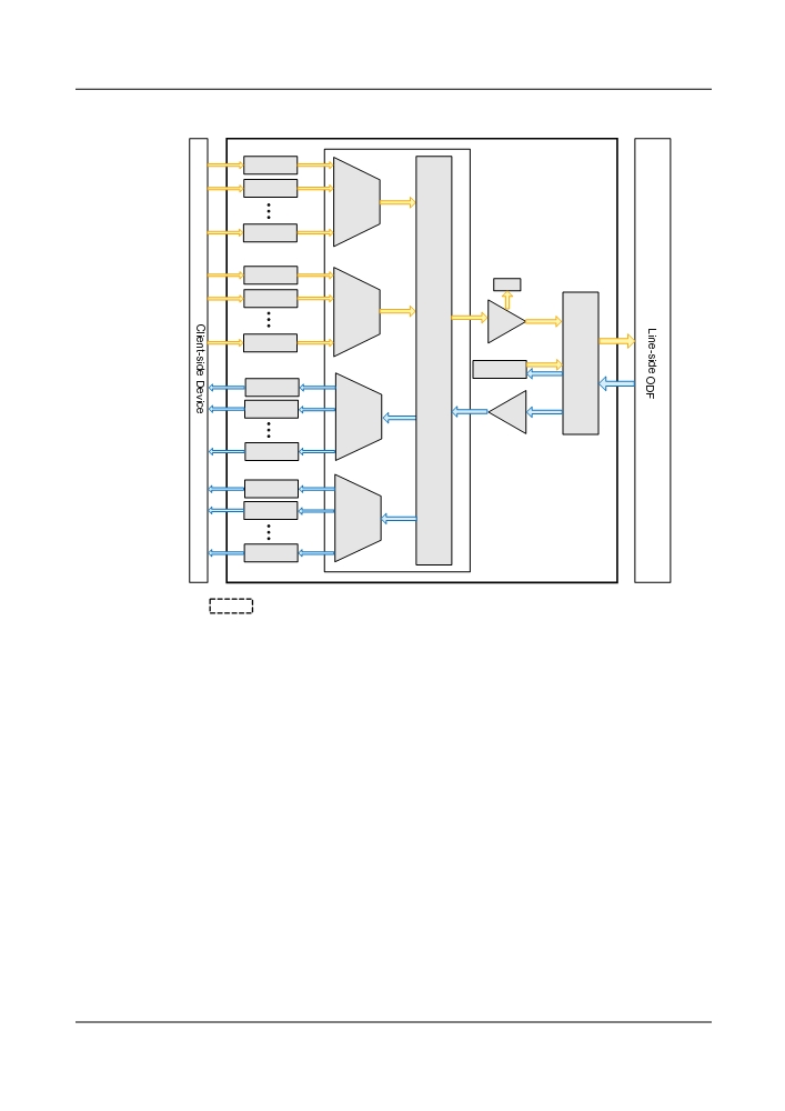
Figure 4-25 Position of the multiplexer and demultiplexer unit
OTU
OTU
OM
(C-ODD)
OTU
OTU
WMU
OTU
OM
OA
(C-EVEN)
OTU
ITL
FIU
SC1
OTU
OTU
OD
OA
(C-ODD)
OTU
OTU
OTU
OD
(C-EVEN)
OTU
: The multiplexer and demultiplexer units
OTU: Optical Transponder Unit
OA: Optical Amplifying Unit
OM: Optical Multiplexer Unit
OD: Optical Demultiplexer Unit
SC1: Unidirectional Optical
FIU: Fiber Interface Unit
Supervisory Channel Unit
ODF: Optical Distribution Frame
ITL: interleaver board
WMU: Wavelength Monitored
Unit
C-ODD: Odd channels in the C band C-EVEN: Even channels in the C
band
The functions of the multiplexer and demultiplexer units are as follows:
l TN11D40/TN12D40: Demultiplexes main path signal to a maximum of 40 channels of
service in C band.
l TN11D40V: Demultiplexes main path signal to a maximum of 40 signals and adjusts the
output optical power of each channel in C band.
l TN11SFIU/TN12FIU/TN13FIU: Realizes the multiplexing and demultiplexing of signals
transmitted by the main path and the optical supervisory channel in C band.
l TN11M40/TN12M40: Multiplexes a maximum of 40 signals into one signal in C band.
l TN11M40V/TN12M40V: Multiplexes a maximum of 40 signals into one signal and adjusts
the input optical power of each channel in C band.
79
l TN11ITL/ TN12ITL: Multiplexes/demultiplexes optical signals between the DWDM
systems with the 100 GHz channel spacing and that with the 50 GHz channel spacing in C
band.
l TN11SFIU: Multiplexes and demultiplexes signals transmitted along the main path and
optical supervisory channel.
4.2.4.9 Fixed Optical Add/Drop Multiplexer Board
In the fixed optical add/drop multiplexer unit, single-wavelength optical signals are added/
dropped from the multiplexed signals and sent to an OTU.
At the same time, the single-wavelength optical signals transmitted at the OTU are multiplexed
into the multiplexed signals.
The fixed optical add/drop multiplexer units include:
l CMR2: CWDM 2-channel optical add/drop multiplexing unit
l CMR4: CWDM 4-channel optical add/drop multiplexing unit
l DMR1: CWDM 1-channel bidirectional optical add/drop multiplexer board
l MR2: 2-channel optical add/drop multiplexing unit
l MR4: 4-channel optical add/drop multiplexing unit
l MR8: 8-channel optical add/drop multiplexing unit
l MR8V: 8-channel optical add/drop multiplexing unit with VOA
l SBM2: single fiber bidirectional 2-channel optical add/drop multiplexing configuration
board
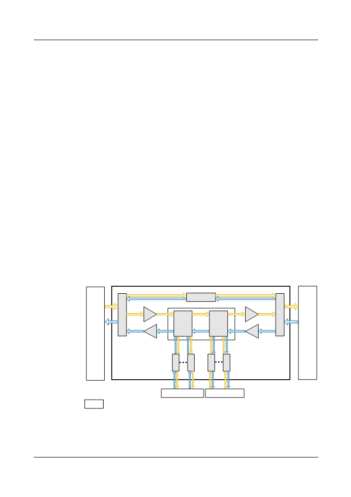
Figure 4-26 shows the position of the fixed optical add/drop multiplexer unit in the system.
Figure 4-26 Position of the fixed optical add/drop multiplexer unit
SC2
East
West
FIU
OA
OA
FIU
line-side
line-side
OADM
OADM
ODF
Unit
Unit
ODF
OA
OA
O
O
O
O
T
T
T
T
U
U
U
U
West client-side
East client-side
: The optical add/drop multiplexer unit
ODF: optical distribution frame
FIU: fiber interface unit
OA: optical amplifier unit
OADM Unit: optical add/drop multiplexer unit SC2: bidirectional OSC unit OTU: optical transponder unit
80