HUAWEI OptiX OSN 8800 T64/T32 Intelligent Optical Transport Platform. Product Description - part 10

5.1 Electrical Layer Grooming
The OptiX OSN 8800 T64/8800 T32 supports the integrated grooming of electrical layer signals.
5.1.1 OTN Centralized Grooming
The OptiX OSN 8800 T32 provides cross-connect boards to achieve centralized cross-
connections and supports full cross-connections between slots IU1-IU8, IU12-IU27, IU29-IU36
with a cross-connect capacity of 40 Gbit/s for each slot. The equipment has a cross-connect
capacity of 1.28 Tbit/s. The equipment supports centralized cross-connections of ODUflex,
ODU0, ODU1, ODU2, and ODU3 signals.
The OptiX OSN 8800 T64 provides cross-connect boards to achieve centralized cross-
connections and supports full cross-connections between slots IU1-IU8, IU11-IU42, IU45-IU68
with a cross-connect capacity of 40 Gbit/s for each slot. The equipment has a cross-connect
capacity of 2.56 Tbit/s. The equipment supports centralized cross-connections of ODUflex,
ODU0, ODU1, ODU2, and ODU3 signals.
Centralized Grooming
Table 5-1 lists the services supported by the tributary board and the line board centralized
grooming.
Table 5-1 Services supported by the tributary board and the line board centralized grooming
Board
Centralized Grooming
TN52ND2
ODU0 signals, ODU1 signals, ODU2/
ODU2e signals
TN53ND2
ODU0 signals, ODU1 signals, ODU2/
ODU2e signals, ODUflex signals
TN52NS2
ODU0 signals, ODU1 signals, ODU2/
ODU2e signals
TN53NS2
ODU0 signals, ODU1 signals, ODU2/
ODU2e signals, ODUflex signals
TN52NS3
ODU0 signals, ODU1 signals, ODU2/
ODU2e signals
TN54NS3
ODU0 signals, ODU1 signals, ODU2/
ODU2e signals, ODU3 signals
TN52NQ2
ODU0 signals, ODU1 signals, ODU2/
ODU2e signals
TN54NQ2
TN53NQ2
ODU0 signals, ODU1 signals, ODU2/
ODU2e signals, ODUflex signals
TN52TDX
ODU2/ODU2e signals
TN53TDX
ODU2/ODU2e signals, ODUflex signals
92
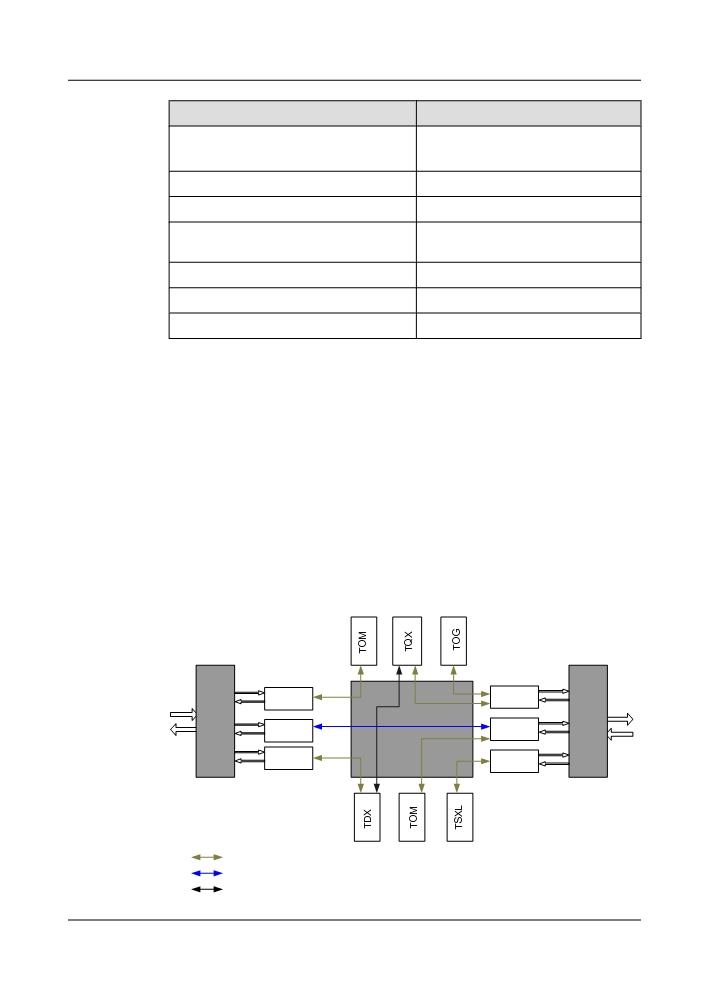
Board
Centralized Grooming
TN52TQX
ODU2/ODU2e signals
TN53TQX
TN55TQX
ODU2/ODU2e signals, ODUflex signals
TN52TOM
ODU0 signals, ODU1 signals
TN54TOA
ODU0 signals, ODU1 signals
, ODUflex signals
TN54THA
ODU0 signals, ODU1 signals
TN52TOG
ODU0 signals
TN53TSXL
ODU3 signals
Application of Electrical-Layer Grooming
Three types of typical application are supported by electrical grooming, for detail, see Figure
5-1.
l Passing through on the client side: The services are input from a client-side port of the local
station and are output through another client-side port. This is, the services are not
transmitted through the fiber line.
l Adding and dropping on the client side: The services of the other stations are transmitted
through the fiber to a WDM-side port of the local station, and then are output through a
client-side port, or the client services are input from the local station and are transmitted to
the other station through the fiber.
l Passing through on the line side: The services are not added or dropped at the local station.
The local station functions as a regeneration station and sends the services from one side
of the fiber line to the other side.
Figure 5-1 Application of electrical-layer grooming
ND2
NQ2
MUX/
MUX/
DMUX
ND2
ND2
Cross-Connect
DMUX
Unit
ND2
NS3
:Adding and dropping on the client side
:Passing through on the client side
:Passing through on the line side
93

5.1.2 OCS Centralized Grooming
When the OptiX OSN 8800 T32 used as an OCS device, it can realize full cross-connection
among the 32 slots of IU1-IU8, IU12-IU27 and IU29-IU36 with the XCM board. It supports a
maximum of 1.28 Tbit/s grooming of VC-4 or 80 Gbit/s grooming of VC-3/VC-12 signals.
When the OptiX OSN 8800 T64 used as an OCS device, it can realize full cross-connection
among the 64 slots of IU1-IU8, IU11-IU42 and IU45-IU68 with the SXM board. It supports a
maximum of 1.28 Tbit/s grooming of VC-4 or 80 Gbit/s grooming of VC-3/VC-12 signals.
Table 5-2 lists the services supported by the SDH service processing boards centralized
grooming.
Table 5-2 Services supported by the SDH service processing boards centralized grooming
Board
Centralized Grooming
EAS2
VC-4 signals
EGSH
VC-12 signals
VC-3 signals
VC-4 signals
SF64A
VC-12 signals
VC-3 signals
VC-4 signals
SF64
VC-12 signals
VC-3 signals
VC-4 signals
SFD64
VC-12 signals
VC-3 signals
VC-4 signals
SL64
VC-12 signals
VC-3 signals
VC-4 signals
SLD64
VC-12 signals
VC-3 signals
VC-4 signals
SLH41
VC-12 signals
VC-3 signals
VC-4 signals
94
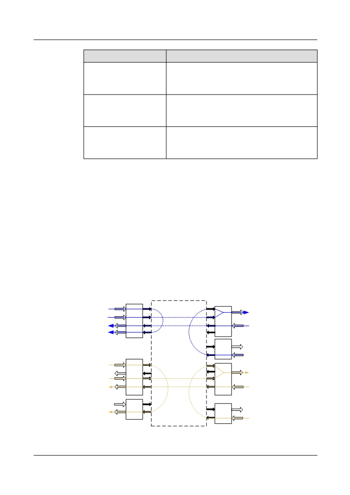
Board
Centralized Grooming
SLO16
VC-12 signals
VC-3 signals
VC-4 signals
SLQ16
VC-12 signals
VC-3 signals
VC-4 signals
SLQ64
VC-12 signals
VC-3 signals
VC-4 signals
Application of Electrical Layer Grooming
The following three types of typical application are supported by electrical grooming.
l Passing through on the client side: The services are input from a client-side port of the local
station and are output through another client-side port. This is, the services are not
transmitted through the fiber line.
l Adding and dropping on the client side: The services of the other stations are transmitted
through the fiber to a WDM-side port of the local station, and then are output through a
client-side port, or the client services are input from the local station and are transmitted to
the other stations through the fiber.
l Passing through on the line side: The services are not added or dropped at the local station.
The local station functions as a regeneration station and sends the services from one side
of the fiber line to the other side.
The application of electrical layer grooming is shown in Figure 5-2.
Figure 5-2 Application of electrical layer grooming
1
Client
A
B
WDM
Side
Side
2
B
Cross-connection Unit
C
C
Client
Line
Side
Side
C
C
A: Tributary unit
B: Line unit
C: SDH unit
95

5.2 Optical Layer Grooming
Distribution solutions of medium wavelength resource of WDM equipment are as follows:
l Fixed optical add/drop multiplexer (FOADM)
l Reconfigurable optical add/drop multiplexer (ROADM)
The FOADM solution cannot adjust the distribution of wavelength resource according to the
service development.
The ROADM solution realizes reconfiguration of wavelengths by blocking or cross-connecting
of wavelengths. This ensures that the static distribution of the wavelength resource is flexible
and dynamic. ROADM with U2000 can remotely and dynamically adjust the status of
wavelength adding/dropping and passing through. A maximum of 80 wavelengths can be
adjusted.
In the case where one link, fiber or dimension fails in the ROADM solution, other links, fibers
and dimensions remain unaffected. This is attributed to three factors: gain locking of optical
amplifiers, service separation and wavelength blocking of the ROADM solution.
The ROADM solution has the following advantages:
5.2.1 Grooming Ability
This section describes the optical-layer service grooming capability of ROADM sites as shown
in Table 5-3.
Table 5-3 Optical-Layer grooming capability
Item
Description
Number of
Grooms a maximum of 80 wavelengths.
wavelengths
Rate
Supports grooming of wavelengths at the rate of 2.5 Gbit/s, 10 Gbit/s,
40 Gbit/s, and 100 Gbit/s.
Dimension
Supports service grooming of two to nine dimensions.
NOTE
Dimensions refer to transmission directions.
Scenario
l Colored & Directioned
l Colored & Directionless
l Colorless & Directionless
96
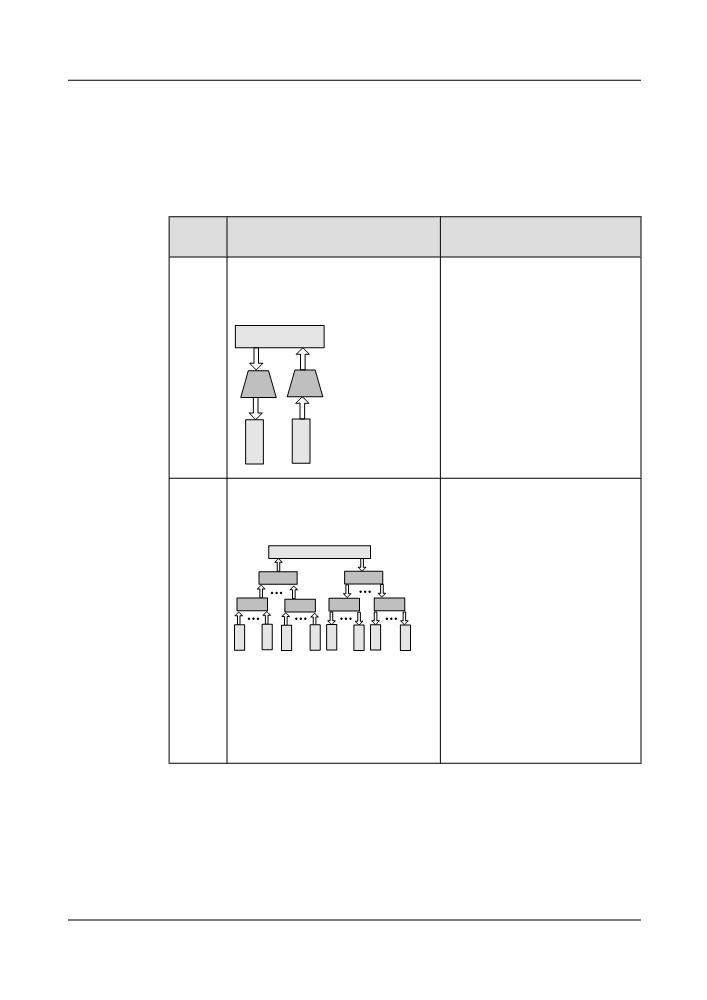
5.2.2 Basic Concept
ROADM application scenarios include colored&directioned, colored&directionless, and
colorless&directionless. For concepts about colored, colorless, directioned, and directionless,
see Table 5-4.
Table 5-4 Basic Concept
Concep
Description
Application
t
Colored
The M40, D40, and M40V boards are
l Colored add/drop ports(fixed
used to add and drop wavelengths. Each
wavelength) have the advantages
add port or drop port can add or drop
of lower insertion loss and lower
fixed wavelengths only.
cost. If new wavelengths need to
replace the existing wavelengths, a
ROADM
site visit is necessary to connect the
line card/OTU colored port to the
matching add/drop port.
D40
M40
l On an ASON network, the services
can be rerouted only on the same
O
O
wavelength, so the wavelengths
may be blocked.
T
T
U
U
Colorles
The WSM9 and WSD9 boards are used
l Colorless add/drop ports(tunable)
s
to add and drop wavelengths. Any
allow remotely provisioned
wavelengths can be added at a port on the
reconfigurability of the ROADM.
board and dropped at the port.
However, the OTU/line boards
ROADM
must be installed in the subrack in
order to automatically provision
WSM9
WSD9
new services. If the OTU/line
boards are not physically present in
WSM9
WSM9
WSD9
WSD9
the subrack, a site visit is necessary
O
O
O
O
O
O
O
O
to install the required boards for
T
T
T
T
T
T
T
T
the new services.
U
U
U
U
U
U
U
U
l On an ASON network, if a
wavelength-tunable OTU or line
board is used in the colorless
scenario, service wavelengths can
be flexibly converted during
rerouting to avoid a wavelength
congestion.
97
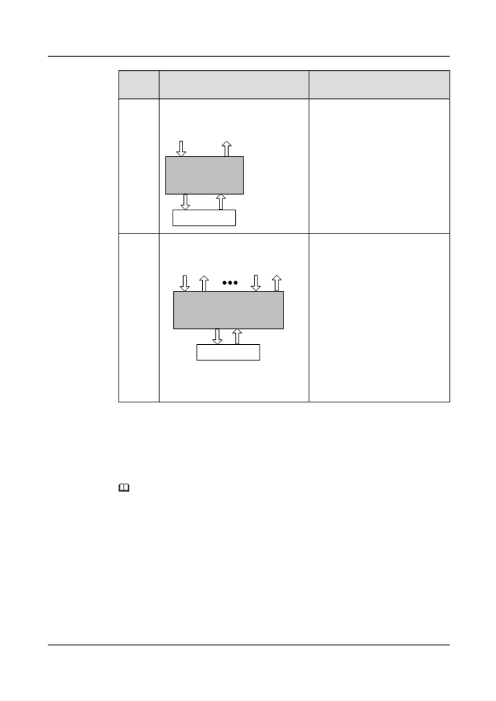
Concep
Description
Application
t
Directio
A local wavelength carrying services can
l In a directioned scenario, the
ned
be transmitted to a specific direction.
current path cannot be adjusted
flexibly. If the current path must be
To Direction 1
adjusted, a site visit is required to
adjust the fiber connections for the
IN
OUT
network.
ROADM
l A directioned scenario applies to
non-ASON networks.
DMx
AMx
Local Service
Directio
A local wavelength carrying services can
l On a non-ASON network, the
nless
be transmitted to any directions.
current path cannot be
automatically adjusted in the
To direction 1
To direction x
directionless scenario. When
services are adjusted or the
AM1
DM1
AMx DMx
protection path is used in case of a
faulty working path, manually
ROADM
configure optical cross-
OUT
IN
connections to achieve flexible
service grooming.
Local Service
l On an ASON network, the
rerouting function automatically
finds a path and automatically
creates an optical cross-
connection.
5.2.3 1-Degree ROADM
This configuration generally applies to a terminal node. Services are not interrupted during
expansion.
NOTE
The WSMD4 in the figure below can be replaced with the RDU9+WSM9, WSD9+WSM9, WSMD2 , or
WSMD9.
The WSMD2 board supports only a 40-channel system, and other board groups support 80-channel systems.
98
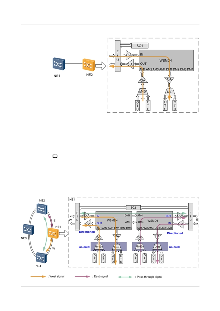
Figure 5-3 1-degree ROADM application
5.2.4 2-Degree ROADM
On a 2-degree ROADM network, services can be transmitted in two directions. To smoothly
upgrade a network to one with over four degrees, configure RDU9+WSM9, WSD9+WSM9, or
WSMD9.
NOTE
The WSMD4 in the figure below can be replaced with the RDU9+WSM9, WSD9+WSM9, WSMD2 , or
WSMD9.
The WSMD2 supports only a 40-channel system, and other board groups support 80-channel systems.
Colored & Directioned Scenario
Figure 5-4 Colored & directioned scenario of the 2-degree ROADM application
99
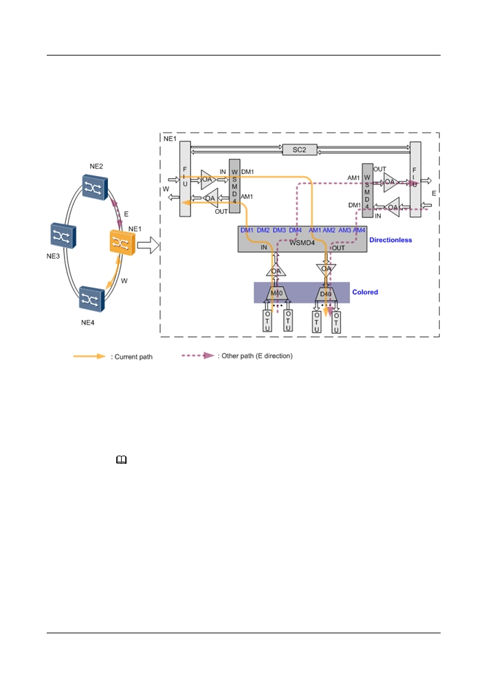
Colored & Directionless Scenario
Figure 5-5 Colored & directionless scenario of the 2-degree ROADM application
5.2.5 3-Degree ROADM
On a 3-degree ROADM network, services can be transmitted in three directions. To smoothly
upgrade a network to one with over four degrees, configure RDU9+WSM9, WSD9+WSM9, or
WSMD9.
NOTE
The WSMD4 in the figure below can be replaced with the RDU9+WSM9, WSD9+WSM9 , or WSMD9.
Colored & Directioned Scenario
Local services are added to the WSMD4 through the AM1 port and then transmitted to the south
through the OUT port. Services from the west and east pass through the AM2 and AM4 ports
on the WSMD4 and head south.
In this scenario, to cross-connect services on NE1 in directions west, south, and east, three groups
of M40+D40 must be configured, so each group corresponds to one direction.
100
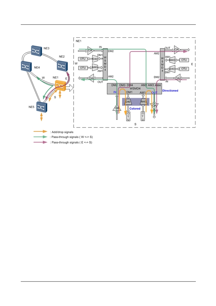
Figure 5-6 Colored & directioned scenario of the 3-degree ROADM application
Colored & Directionless Scenario
Services on NE1 can be transmitted along paths in direction west, north, or east.
l To adjust the current path (for example, when services are adjusted or the protection path
is used in case of a faulty working path), manually configure optical cross-connections to
achieve flexible service grooming.
l On an ASON network, the rerouting function automatically finds a path and automatically
creates an optical cross-connection to ensure proper service transmission on NE1. In the
colored scenario, only the same wavelength can be used for service rerouting.
In this scenario, to cross-connect local services on NE1 in direction west, north, or east, only
one group of M40+D40 is required.
101
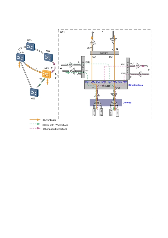
Figure 5-7 Colored & directionless scenario of the 3-degree ROADM application
Colorless & Directionless Scenario
Services on NE1 can be transmitted along paths in direction west, north, or east.
l To adjust the current path (for example, when services are adjusted or the protection path
is used in case of a faulty working path), manually configure optical cross-connections to
achieve flexible service grooming.
l On an ASON network, the rerouting function automatically finds a path and automatically
creates an optical cross-connection to ensure proper service transmission on NE1. If a
wavelength-tunable OTU or line board is used in the colorless scenario, service
wavelengths can be flexibly converted during rerouting to avoid a wavelength congestion.
102