HUAWEI OptiX OSN 8800 T64/T32 Intelligent Optical Transport Platform. Product Description - part 17
corresponding physical channel in the physical layer through the MAC connection.
Otherwise, the MAC layer discards the data frame.
l
Network layer
The main function of the network layer is to provide the route addressing for data frames
and the route management for the DCC communication network. The network layer
performs the following functions:
- Establishes and maintains ECC routes.
Each route item includes the following information: address of the destination NE,
address of the transfer NE, transfer distance (the number of passed transfer NEs), route
priority (The priority value ranges from 1 to 7. The priority of an automatically
established route is 4 by default. The system always selects the route with the highest
priority.), and mode (0 represents the automatic route and 1 represents the manual route).
- Provides the data communication service.
The network layer receives the packet transferred from the MAC layer. If the destination
address of the packet is the local station, the network layer transfers the packet to the
transport layer. Otherwise, the network layer requests the MAC layer to transfer the
packet to the transfer station according to the route item that matches the destination
address in the network layer routing table.
The network layer sends the packet from the transport layer. The network layer requests
the MAC layer to transfer the packet to the transfer station according to the route item
that matches the destination address of the packet in the network layer routing table.
l
Transport layer
The main function of the transport layer (L4 layer) is to provide the end-to-end
communication service for the upper layer. As the communication between the OptiX
equipment and the U2000 is controlled by the end-to-end connection-oriented service in
the application layer, the L4 layer provides only the end-to-end connectionless
communication service, that is, transparent data transfer service.
NOTE
In the HWECC protocol stack, the NE address used by each layer is the ID of the NE. The NE ID has 24
bits. The highest eight bits represent the subnet ID (or the extended ID) and the lowest 16 bits represent
the basic ID. For example, if the ID of an NE is 0x090001, the subnet ID of the NE is 9 and the basic ID
is 1.
Extended HWECC
The physical layer of the ECC is DCC, whose data is transmitted based on the fiber. In certain
cases, the network or NE may be independent and there is no DCC channel to the gateway NE
(no fiber connection). The extended ECC refers to the ECC protocol stack that is loaded on the
TCP/IP protocol stack. That is, the HWECC protocol stack is carried through the extended
channel (such as Ethernet) instead of the DCC channel to meet the requirements of special
scenarios. The difference between the extended ECC and the ECC is that the physical layer of
the ECC is the DCC channel and that of the extended ECC is an extended channel (such as
Ethernet channel). Figure 5-52 shows the networking environment with the extended ECC. The
communication protocol between NE6 and NE7 is extended ECC.
169

Figure 5-52 Networking environment with the extended ECC
GNE1
NE7
NE12
NE6
NM
HUB1
HUB2
NE2
NE5
NE8
NE11
Network cable
NE3
NE4
NE9
NE10
Fiber
Subnet 1
Subnet 2
IP over DCC Protocol Stack
The IP over DCC protocol consists of five layers, as shown in the following figure.
Figure 5-53 Architecture of the IP over DCC protocol stack
Routing protocol
OSPF/RIP
Transport layer
TCP/UDP
Network layer
IP
Data link layer
PPP
Ethernet
Physical layer
DCC
l Physical layer
The main function of the physical layer is to provide channels for data transmission for the
data end equipment.
Physical channels are classified into the following two categories:
- DCC channel: The SDH-frame DCC bytes or the OTN-frame GCC bytes are used as
the channels for the communication between NEs.
- Ethernet physical channel: The NE provides the Ethernet physical channel through the
Ethernet NM port or the NE cascading port.
l Data link layer
The main function of the data link layer is to provide reliable data transmission on physical
links.
170

In the case of DCCs, the NE adopts the PPP protocol to realize the data link layer function.
The PPP protocol complies with RFC 1661.
l
Network layer
- The main function of the network layer is to specify the network layer address for a
network entity and to provide the transferring and addressing functions.
- The NE adopts the IP and the matching ARP and ICMP to realize the network layer
functions.
l
Transport layer
The main function of the transport layer is to provide the end-to-end communication service
for the upper layer. The NE supports the connection-oriented TCP and the connectionless-
oriented UDP.
l
Routing protocols
Routing protocols belong to the scope of the application layer. The NE supports the two
routing protocols, open shortest path first (OSPF) and routing information protocol (RIP).
By default, the NE uses the OSPF protocol. The RIP protocol is used only when the
interconnected third-party equipment does not support the OSPF protocol.
The OSPF protocol is a dynamic routing protocol that is based on the link status. The OSPF
protocol divides an autonomous system into several areas. Route nodes exchange routing
information in an area. The route nodes at the edge of an area make summary and exchange
information with the routers in other areas. Areas are identified by area IDs. The area ID
has the same format as the IP address.
Currently, the OSPF protocol of the OptiX equipment supports only the routes within an
area and does not support the routes between areas. Hence, the gateway NE and all its
managed non-gateway NEs must be in the same OSPF area. By default, the line port of the
OptiX equipment is enabled with the OSPF protocol but the Ethernet port is not enabled
with the OSPF protocol. Hence, to form a network through the Ethernet port, you need to
modify the OSPF setting of the NE.
In addition to the dynamic routing protocol, the NE supports static routes. Static routes are
manually configured routes. Static routes have a higher priority than dynamic routes. When
there is a route conflict, the equipment selects static routes.
OSI over DCC Protocol Stack
The OSI over DCC protocol consists of five layers, in which the session layer, representation
layer, and application layer are unified as the application layer and use proprietary protocols, as
shown in Figure 5-54.
Figure 5-54 Architecture of the OSI over DCC protocol stack
Qx/MML/SWDL
Application layer
Transport layer
TP4
Network layer
IS-IS/ES-IS/CLNP
LAPD
Data link layer
Ethernet
DCC
Physical layer
171
5.11.2.3 DCN Solution Classification by Physical Resource
Inband port
When inband DCN is used, the network management messages are encapsulated in data service
frames and are transmitted with packet services over service channels. In the transmission
process, special VLAN tags or MPLS labels are used. This means that interconnection with
third-party equipment at the network layer is not feasible (except when the transparent
transmission solution is used).
Outband Port
Outband port can be used for ASON based on the split of optical and electrical NEs; The Huawei
WDM/OTN equipment can be interconnected with third-party equipment at the network layer.
NMS Port
NMS ports enable WDM/OTN equipment to access the NMS, provide an extended ECC
channel, or interconnect to third-party equipment at the network layer.
Transparent transmission
This solution is applicable to the scenario where NG WDM equipment is networked with other
WDM equipment (For example: NG WDM equipment lets signals from OptiX BWS 1600G
pass through), and the scenario where WDM/OTN equipment lets signals from third-party
equipment pass through.
5.11.3 Huawei DCN Management Capability
This chapter describes the DCN management capabilities of Huawei equipment and the rules
for planning DCN on Huawei equipment.
This following generally describes the DCN management capabilities and DCN planning rules
specific to each DCN solution. For more details, see the Feature Description.
HWECC Solution
l There should not be too many gateway NEs on a network. Otherwise, the network
performance may be affected. It is suggested that the number of gateway NEs managed by
an NMS does not exceed 2000. If the number exceeds 2000, use extended ECC to combine
the gateway NEs.
l In the actual networking, the gateway NE has the largest traffic volume. To ensure stable
communication, select the equipment with strong ECC processing capability as the gateway
NE. The gateway NE and other NEs should form a star network, to reduce the traffic volume
of other NEs.
l The number of HWECC subnet NEs should not exceed 50 and the number of NEs for each
gateway NE should not exceed 200. Each GNE is suggested to manage no more than 100
NEs.
172
l In the hybrid networking of different OptiX equipment, the number of HWECC subnet
NEs should not exceed 50 and the number of NEs for each gateway NE should not exceed
50.
l Do not enable the ECC communication between different HWECC subnets. That is,
- Do not use network cables or fibers to establish the direct physical connection between
any NEs in two HWECC subnets.
- Use the U2000 to disable the ECC communication between NEs in different HWECC
subnets.
l In the application where the extended ECC communication is required, the manually
extended ECC is recommended. Do not use the automatically extended ECC, so that the
bandwidth between NEs using extended ECC for communication is saved.
l When the number of Huawei equipment that uses the extended ECC communication
exceeds eight, the manually extended ECC communication must be used.
l When configuring the manually extended ECC, configure one or more NEs as the server
and other NEs as the client. One server NE can have a maximum of seven client NEs. If
the number of client NEs managed by a server NE exceeds eight, select a client NE as the
server NE for the remaining client NEs. In this case, the client NE functions as a client and
a server at the same time. The rest may be deduced by analogy. The port numbers of the
server NEs must be different.
IP over DCC Solution
l When the U2000 is used to manage NEs, the number of non-gateway NEs accessed through
one gateway NE cannot exceed 64.
l The gateway NE and the non-gateway NEs that are managed by the gateway NE must be
in the same OSPF area.
l The number of NEs in an OSPF area cannot exceed 64.
l Plan static routes when the U2000 and the gateway NE or the NEs that need to be directly
accessed by the U2000 cannot be interconnected through the dynamic route at the network
layer.
l If the network is comprised of only the OptiX equipment, it is recommended that you use
bytes D1 to D3 in SDH frames as DCCs.
l If the network is comprised of both OptiX equipment and the third-party SDH equipment,
use the DCC bytes that are used by the third-party equipment (for example, bytes D1 to D3
or D4 to D12) as DCCs.
OSI over DCC Solution
l Only the node at the end of a network can be configured as an ES. The limited route
resources of an ES affect the network expansion. Therefore, it is not suggested to configure
the equipment as an ES. The U2000 works as an ES.
l L1-IS is the default node type of Huawei products. It supports only intra-area routing (Level
1 routing).
l If inter-area routing (Level 2 routing) is required, set the network node type of the equipment
to L2-IS. L2-IS maintains two routing tables at the same time: one is used for intra-area
routing and the other for inter-area routing.
l The OptiX equipment supports IS-IS Level 2 routing. When the OSI communication
protocol is used, you need to divide the network into areas according to the network size.
The number of areas, also the number of Level 2 NEs, on the entire DCN cannot exceed
173
32. A gateway NE is a Level 2 NE. The number of Level 1 NEs that a gateway NE have
cannot exceed 32.
l
If the number of NEs in a network is smaller than 32, you do not need to divide the network
into areas. In this case, set the node type of all NEs to L1-IS, and set the AREA IDs in the
NSAP area addresses of all NEs to the same value. In the case of a large-scale network,
comply with the following principles to divide the network:
- Divide the DCN into several areas to manage.
- Set several NEs in each area to L2-IS. Two NEs in each area are recommended because
the two can be of mutual backup.
- In the DCN, all L2 equipment must be arranged in a continuous manner.
l
When all nodes in the DCN network run the OSI protocol stack, do not configure all NEs
as gateway NEs. Configure certain NEs as gateway NEs. Configure the other NEs as non-
gateway NEs and specify a gateway NE for a non-gateway NE. The number of non-gateway
NEs under one gateway NE cannot exceed 32. Otherwise, the gateway NE is overloaded,
and the performance of the U2000 is decreased.
l
When dividing a network to support layered routes, configure one or several NEs in each
area as gateway NEs. When creating a non-gateway NE, specify a gateway NE in the local
area for the NE.
l
If the network is comprised of only the OptiX equipment, it is recommended that you use
bytes D1 to D3 in SDH frames as DCCs.
l
If the network is comprised of both OptiX equipment and the third-party SDH equipment,
use the DCC bytes that are used by the third-party equipment (for example, bytes D1 to D3
or D4 to D12) as DCCs.
l
For the two ends of a DCC, set the LAPD role to User at one end and to Network at the
other end.
5.12 Network Management Tools and Protocols
The NM system manages alarm, performance, configuration, communication, security, and
topology of the entire optical transmission system.
The NM system also provides end-to-end management according to the requirements of the user.
The NM system improves the network quality, lowers the maintenance cost, and ensures
reasonable utilization of the network resource.
The NM system provides user friendly interfaces and comprehensive functions. Its software
system adopts component technology and object-oriented technology so that the application sub-
systems can be tailored according to the requirements of the user. This facilitates system
expansion.
5.12.1 U2000
The iManager U2000 (U2000) is Huawei's major and future-proof network management product
and solution.
The U2000 is an integrated management platform for all Huawei equipment. It can centrally
manage transport equipment, access equipment, and IP equipment (including routers, security
equipment, and Metro Ethernet equipment). The U2000 is designed as the management system
for Huawei equipment and provides powerful management functions at the NE and network
layers.
174
In the TMN, the U2000 is located on the element management layer and network management
layer, and thus it supports all functions of the NE and network layers.
5.12.2 Web LCT
The iManager U2000 Web local craft terminal is abbreviated as Web LCT.
The Web LCT uniformly manages Huawei OptiX series optical transmission equipment, such
as the SDH and WDM equipment. Based on the browser/server architecture, the Web LCT
provides the ability to configure and maintain individual NEs. It also provides the ability to
manage alarms, configuration, performance and security.
5.12.3 Simple Network Management Protocol
The system provides the simple network management protocol (SNMP).
The SNMP is a standard protocol based on user datagram protocol (UDP). With an SNMP
compatible management interface, any NM system can query the alarms and performance of the
equipment.
5.12.4 NTP Protocol
Basic Concept
The system supports the Network Time Protocol (NTP). The NTP is used to synchronize the
distributed time server and the client.
The NTP defines the data formats, algorithms, entities and protocols used during the realization
of the protocol:
l The NTP is based on Internet Protocol (IP) and User Datagram Protocol (UDP). It can also
be used by other protocols.
l The NTP develops from time protocol and Internet Control Message Protocol (ICMP)
timestamp message. It has special design for correctness and robustness.
l The NTP defines the mechanism of time synchronization. In theory, the accuracy can reach
a billionth of a second.
l The NTP specifies the features of the local clock, time server, and the method used to
estimate the time difference between the local clock and time server.
l The NTP describes the clock-filter algorithm and clock select algorithm during the
realization of the protocol. When there are multiple time servers in the network, the system
selects the algorithm to calculate the time offset of each time server to improve the accuracy
of the local clock.
Function Implementation
For the working principle of the NTP, see Figure 5-55.
175
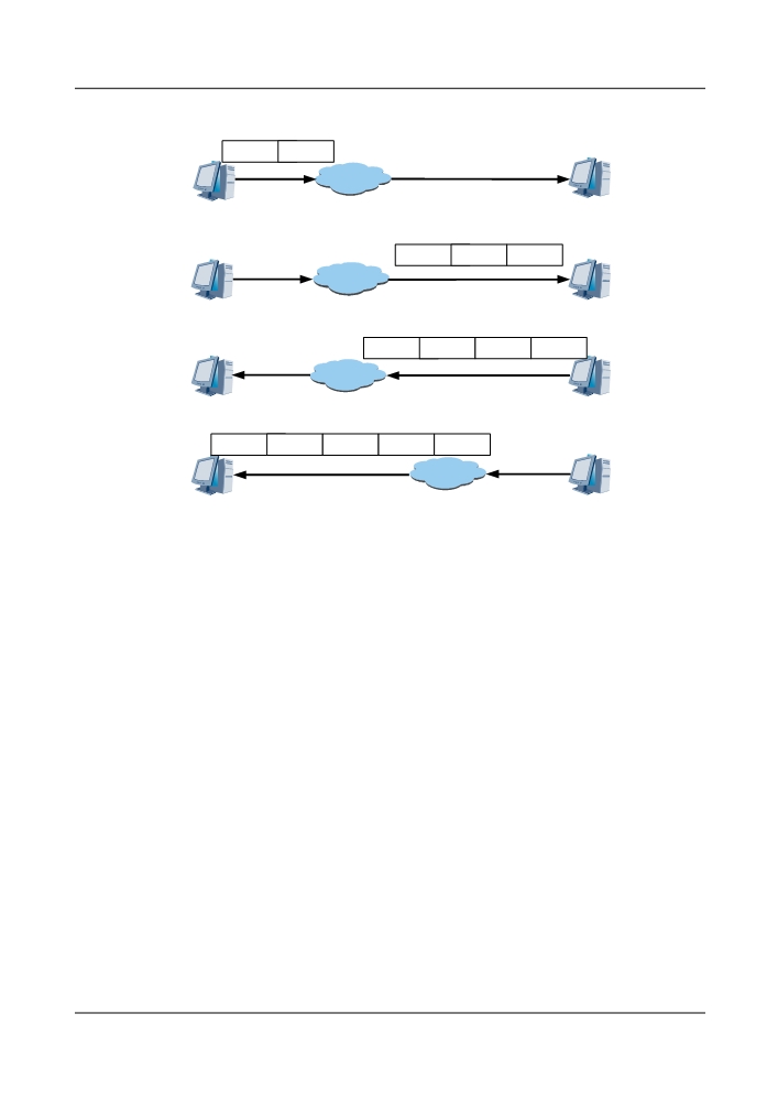
Figure 5-55 Principle of the NTP
NTP
10:00:00
message
am
Network
Server
Client
NTP
10:00:00
10:00:05
message
am
am
Network
Client
Server
NTP
10:00:00
10:00:05
10:00:08
message
am
am
am
Network
Client
Server
NTP
10:00:00
10:00:05
10:00:08
10:00:14
message
am
am
am
am
Network
Client
Server
The process of the system synchronization is as follows:
l The client sends an NTP message to the server. The message capsule has a timestamp that
records the time when the capsule leaves the client. The timestamp is 10:00:00 am.
l When the NTP message capsule reaches the server, the server adds its own timestamp to
the message capsule. This timestamp is 10:00:05 am.
l When the NTP message capsule leaves the server, the server adds its own timestamp to the
message capsule once again. This timestamp is 10:00:08 am.
l Receiving the returned message capsule, the client adds a new timestamp. This timestamp
is 10:00:14 am.
After this process, the client has enough information to calculate two important parameters:
l Round-trip delays of an NTP message
l Clock offsets between the client and the server
The client can set its own clock and keep synchronization with the server based on this
information.
Application
For the synchronization of the network, see Figure 5-56.
176
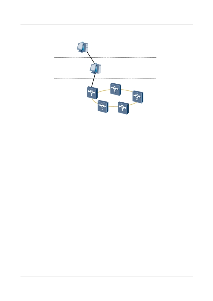
Figure 5-56 Synchronization of the network
The highest level
time server
Other time server
The middle level
time server
NM server
NE 2
Clients
NE 1
NE 3
NE 5
NE 4
As shown in Figure 5-56, the equipment in the synchronized network can be classified into three
categories:
l The highest level time server, referring to the 0-level time server.
l The middle level time server, referring to the 1- or 2-level time server that obtains time
from the higher-level time server and provides time services for the lower-level time server.
l Clients, obtaining time without providing time services.
In application, choose the server and the client in the following way:
l Choose the network management server as the time server for the NE equipment. The
network management server can be set as the highest-level time server or set to obtain time
from other time servers.
l The 8800 NE can be only the client, obtaining time from the specified time server.
5.13 License Control
When creating the NE or the slave subrack on the U2000, you need to configure license. The
U2000 distributes the license files to the corresponding NEs. In this manner, the management
of service capacity and service types is realized.
5.13.1 Service Capacity License
When creating the OptiX OSN 8800 NE or the slave subrack on the U2000, you need to configure
license. The U2000 distributes the license files to the corresponding NEs. In this manner, the
management of service capacity and service types is realized.
177

License and Service Capacity Management
According to the electrical cross-connect capacity and the service type in a subrack, the license
authorizes electrical cross-connect capacity and electrical cross-connect service type for each
subrack. You need to configure the service type and service capacity for every subrack.
For more information, refer to Table 5-25.
Table 5-25 License information table
Subrack Type
Service
Service Capacity
Cross-Connect
Type
Granularity
OptiX OSN 8800
OTN
360G, 720G, 1.28T, 2.56T
ODU0, ODU1, ODU2,
T64
ODU3, ODUflex
SDH
360G, 720G, 1.28T
VC4, VC3, VC12a
Hybrid
360G, 720G, 1.28T,
ODU0, ODU1, ODU2,
2.56T, 6.4Tc
ODU3, VC4, VC3, VC12
None
0G
-
OptiX OSN 8800
OTN
360G, 720G, 1.28T
ODU0, ODU1, ODU2,
T32
ODU3, ODUflex
SDH
360G, 720G, 1.28T
VC4, VC3, VC12b
Hybrid
360G, 720G, 1.28T
ODU0, ODU1, ODU2,
ODU3, VC4, VC3, VC12
None
0G
-
a: The OptiX OSN 8800 T64 subrack supports a maximum of 80 Gbit/s VC-3/VC-12 cross-
connections, and supports a maximum of 1.28 Tbit/s VC-4 cross-connections.
b: The OptiX OSN 8800 T32 subrack supports a maximum of 80 Gbit/s VC-3/VC-12 cross-
connections, and supports a maximum of 1.28 Tbit/s VC-4 cross-connections.
If the subrack has no electrical cross-connections, set the service type to None and the service
capacity to 0G.
The OptiX OSN 8800 T32 supports the cross-connection of ODU3/ODU2/ODU1/ODU0/
ODUflex/VC-4/VC-3/VC-12 (maximum rate of 1.28 Tbit/s), and the OptiX OSN 8800 T64
supports the cross-connection of ODU3/ODU2/ODU1/ODU0/ODUflex/VC-4/VC-3/VC-12
(maximum rate of 2.56Tbit/s). When the cross-connection of ODU3/ODU2/ODU1/ODU0/
ODUflex is required, set the service type to OTN. When the cross-connection of VC-4/VC-3/
VC-12 is required, set the service type to SDH. When the service type is Hybrid, the cross-
connections of the OTN service and the SDH service can be realized. Set the service capacity
according to the service planning and the electrical cross-connection service for each subrack.
5.14 Features of Upgrade and Maintenance
178
5.14.1 Software Package Loading
The system supports software package loading to load, upgrade, activate, and manage the NE-
level software in a centralized manner. This simplifies operations when upgrading the NE-level
software.
You can check whether the board software versions match when the board is in service. Once a
board is in service, the board software versions can be automatically updated.
The software package loading has the following features:
l Users load the software in a uniform operation interface.
l After the package loading, the complete software package is stored on the SCC board. The
NE software is directly placed in the target directory while the board software is buffered
in the CF. In this way, the board software can be automatically updated after a new board
is inserted. If the board software files are lost, these files can be restored from the SCC
board.
l The NE can be automatically managed. If the board that is newly inserted does not match
the software of the NE, an auto-update is performed.
l The software package loading is an incremental scheme and is performed to load only the
required files.
l The software package loading supports automatic rollback. When the software or hardware
of the system is faulty, the loading fails and the system restores the original NE software.
The software package loading also supports manual rollback. When errors occur during
the software loading, manual rollback can be performed to restore the original NE software.
The software package loading is applied in the following scenarios:
l Upgrading NE software
l Replacing service boards
l Replacing the SCC board
5.14.2 PRBS Error Detection Function
Certain OTUs of the OptiX OSN 8800 provide the pseudo random bit sequence (PRBS) error
detection function. On the U2000, the meter board can be configured to send PRBS signals, and
the client side and WDM side of the auxiliary board to transparently transmit the PRBS signals.
In this manner, you can perform the bit error test on the transmission link without attaching a
test meter to the equipment during the deployment.
Function Description
In the PRBS test, the OTU can function as either a meter board or an auxiliary board. The meter
board generates and transmits the PRBS signal to the client side of the auxiliary board at the
near end. Then, the auxiliary board at the near end transparently transmits the PRBS signal to
the auxiliary board at the far end. The auxiliary board at the far end loops back the PRBS signal
by configuring a WDM-side or client-side loopback or by applying a physical fiber loopback
on the board.
Application
The OptiX OSN 8800 supports PRBS test on the WDM side and the client side. Figure 5-57
and Figure 5-58 show the networking of the two applications.
179