HUAWEI OptiX OSN 8800 T64/T32 Intelligent Optical Transport Platform. Product Description - part 3
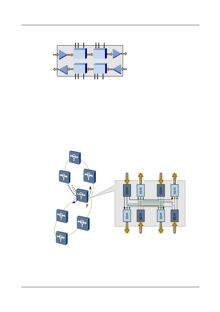
Figure 3-2 Functional diagram of a WSS-based ROADM node
4/8
4/8
…
…
…
…
OAU
OAU
WSD9
WSM9
OAU
WSM9
WSD9
OAU
…
…
…
…
4/8
4/8
WSS realizes colorless wavelength add/drop. Users can set the add/drop or pass-through state
of wavelengths on the NMS. In addition, the dynamic wavelength status can be adjusted remotely
and the services can be fast provisioned.
WSS supports the wavelength grooming in multiple directions and the multi-dimensional
ROADM structure. With WSS, the wavelength resources of multi-directional node on a ring
with chain or intersecting rings network are reconfigurable, as shown in Figure 3-3.
Figure 3-3 Inter-ring grooming ROADM solution
C
D
B
East
South
A
West
South
E
West
North
F
3.2.2 Application of Electrical-Layer Grooming
The OptiX OSN 8800 grooms services by means centralized cross-connections.
15
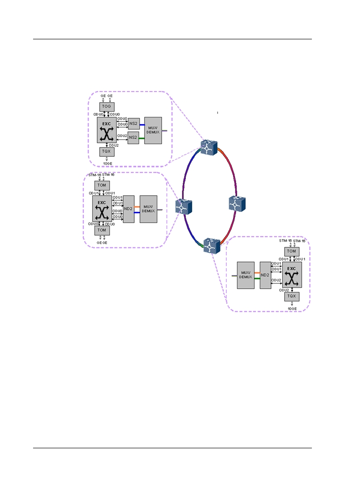
The OptiX OSN 8800 supports ODUflex, ODU0, ODU1, ODU2, and ODU3 cross-connections.
GE, 2.5G, and 10G services can share bandwidth to improve bandwidth utilization. As shown
in Figure 3-4, a GE service and a 2.5G service share a wavelength.
Figure 3-4 Application of electrical-layer grooming
3.2.3 Optical-Electrical Convergence Solution
At the service access end, the equipment cross-connects multi-rate services to 40G channels for
transmission. At a service pass-through station, the equipment fast transmits services by means
of ROADM optical cross-connections. At the service receive end, the equipment drops 40G
services from the line by processing electrical-layer cross-connections. If a wavelength conflict
occurs during optical-layer cross-connections, the equipment can convert wavelengths by means
of electrical-layer cross-connections. In addition, when the transmission distance exceeds the
limit, electrical regeneration can be used. As shown in Figure 3-5, the wavelengths of two
services conflict. In this case, wavelengths can be converted by means of electrical-layer cross-
connections. When the performance of the line deteriorates and results in bit errors, electrical
regeneration can be used to transmit services.
16
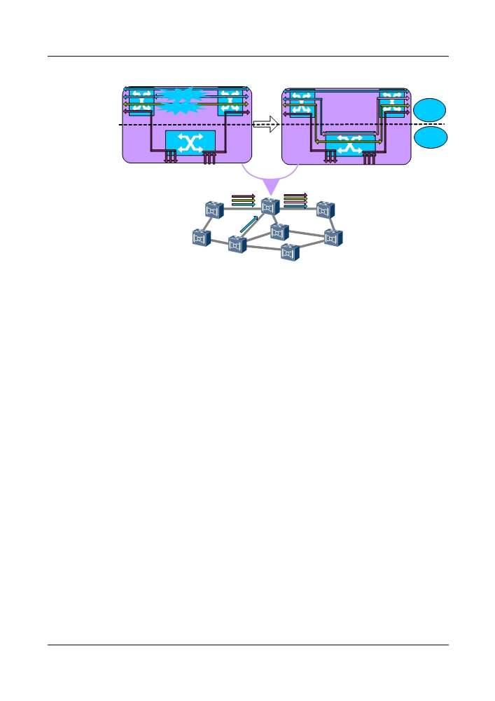
Figure 3-5 Application of electrical-layer grooming
Wavelength conflict
Optical
Bit errors
Layer
Grooming
Electrical
Layer
Grooming
STM-1/GE/2.5G/10G&40G
3.2.4 WDM ASON Solution
The equipment supports the ASON control plane. With the ASON control plane and WDM
features such as ROADM, FOADM, and optical wavelength/sub-wavelength protection, the
equipment provides an ideal WDM ASON solution.
At the core layer of a network, a mesh network is built with WSS/ROADM for wavelength
rerouting. At network edges, ring and chain networks are built with traditional FOADM, OTM,
or PLC ROADM, as the service volume is low and fiber resources are insufficient. For details,
see Figure 3-6.
An ASON network provides the same protection solutions as a traditional network does. In
addition, GMPLS and WSS together provide wavelength rerouting for services under no
protection or 1+1 protection on a mesh network. This helps improve survivability of services.
17
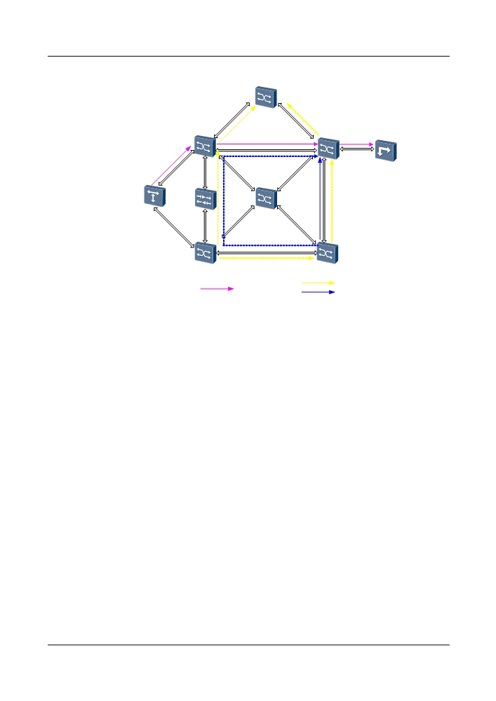
Figure 3-6 WDM ASON solution
PLC ROADM
C
D
OTM
OLA
FOADM
WSS ROADM
A
B
Non-protection
1+1 Protection
Services
Services
3.2.5 PID Solution
This section describes typical PID application.
PID helps to effectively eliminate bandwidth and O&M bottlenecks on a WAN, leveraging the
features such as large capacity, high integration, versatile multi-service access, small size, and
environment-friendly design. On a WAN, a 40G/80G/120G/200G aggregation ring based on
PID boards only is recommended, eliminating commissioning while enabling quick service
provision.
Typical network 1: WAN for a small or medium-sized city
At the OTN aggregation layer, two to six aggregation rings can be deployed with two to four
NEs in each ring. A PID board(s) is used on each NE's line side. Build a 40G/80G/120G/
200G network using PID groups as required. On each aggregation ring, services are electrically
regenerated by the PID and cross-connect boards at each site. NEs at the OTN backbone layer
are interconnected with NEs on aggregation rings through PID boards. Figure 3-7 shows the
details.
18
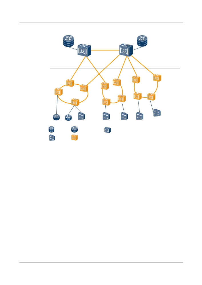
Figure 3-7 WAN for a medium or large-sized city
40/80x10G
Backbone layer
Aggregation layer
200G ring
40G/80G ring
120G ring
: Router
: High-end router
: NG WDM equipment
: BRAS
: PID-installed NG WDM equipment at the aggregation layer
Typical network 2: WAN for a medium or large-sized city
At the OTN aggregation layer, 13 to 20 aggregation rings can be deployed with two to four NEs
in each ring. A PID board(s) is used on each NE's line side. Build a 40G/80G/120G/200G network
using PID groups as required. On each aggregation ring, services are electrically regenerated by
the PID and cross-connect boards at each site. NEs at the OTN backbone layer are interconnected
with NEs on aggregation rings through PID boards. Figure 3-8 shows the details.
19
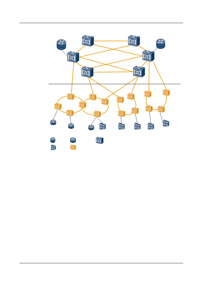
Figure 3-8 WAN for a medium or large-sized city
80x40G Mesh
Backbone
layer
Aggregation
layer
200G ring
40G ring
80G ring
120G ring
: Router
: High-end router
: NG WDM equipment
: BRAS
: PID-installed NG WDM equipment at the aggregation layer
3.3 Typical OCS Networking
3.3.1 Networking for Multi-Granularity Service Grooming, Service
Convergence and Bandwidth Switching
The OptiX OSN 8800 can provide the networking application of the multi-granularity service
grooming and service convergence functions.
Figure 3-9 shows the networking application of the multi-granularity service grooming and
service convergence functions of the OptiX OSN 8800. The OptiX OSN 8800 implement the
large-capacity grooming of STM-64, STM-16, STM-4, STM-1 services. The OptiX OSN OptiX
OSN 8800 can form a hybrid network with different equipment such as DWDM and MSTP.
20
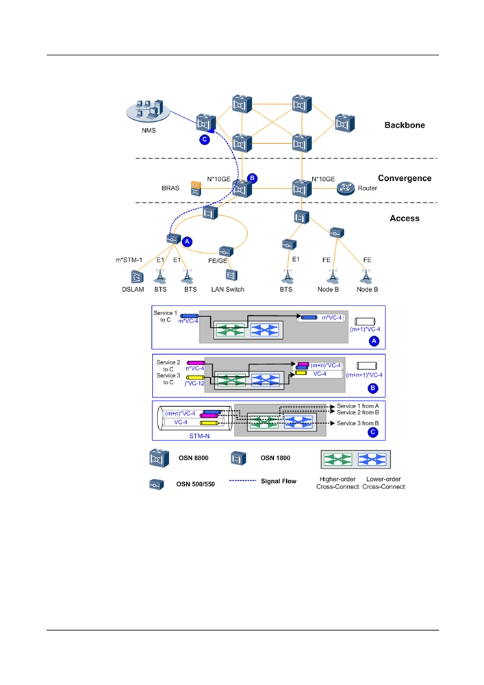
Figure 3-9 Networking configuration of the OptiX OSN 8800 performing multi-granularity
service grooming and service convergence
3.3.2 Networking Application of Ethernet Services
The networking application of Ethernet services includes point-to-point networking for the GE/
10GE service, Layer 2 switching networking for the GE/10GE service, and transparent
transmission networking for the GE service.
Point-to-Point Networking for the GE/10GE Service
A large and flexible bandwidth is required by Internet service provider (ISP) and application
service provider (ASP) for efficient service connection. The OptiX OSN 8800 provides a direct
21
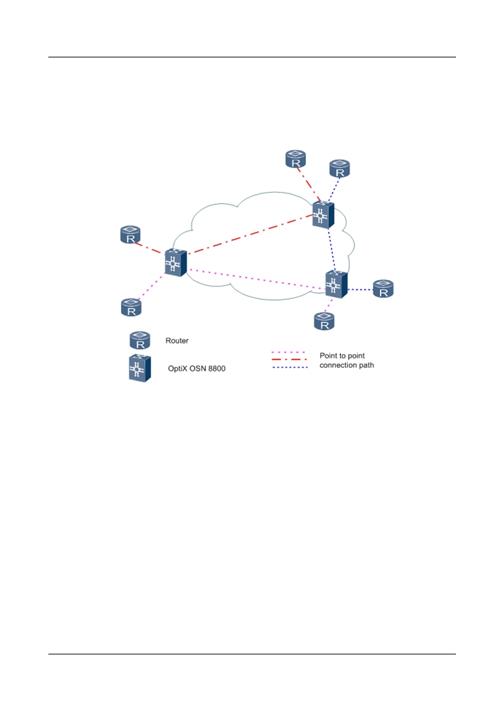
GE service interface. Therefore, the point-to-point transmission of the Ethernet services over a
long distance can be realized over the SDH networks.
Figure 3-10 shows the flexible networking modes of the OptiX OSN 8800. The network can be
a chain, a ring, a mesh network or a combination of these three modes.
Figure 3-10 Point-to-point connection of the GE/10GE service
Layer 2 Switching Networking for the GE/10GE Service
The OptiX OSN 8800 equipment provides the Layer 2 switching boards to achieve the Layer 2
switching from a GE/10GE service to a GE/10GE service.
22
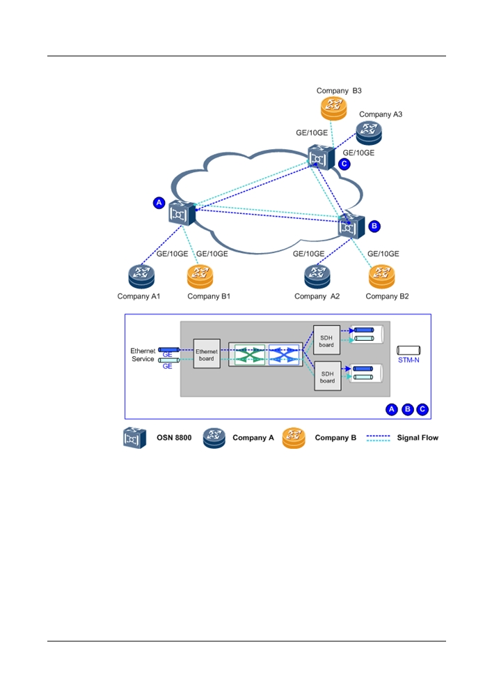
Figure 3-11 Transparent Transmission Networking for the GE/10GE Service
Transparent Transmission Networking for the GE/10GE Service
The Layer 2 switching boards of the OptiX OSN 8800 equipment can transparently transmit the
GE/10GE service. Moreover, it can be directly accessed to a router.
23
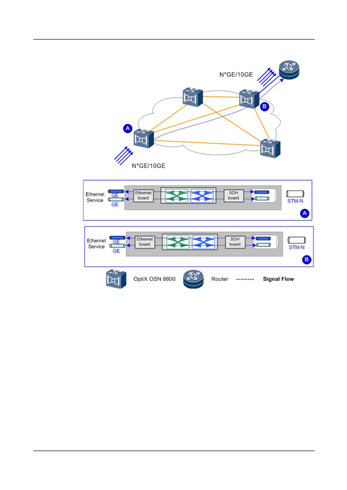
Figure 3-12 Transparent transmission of GE/10GE services
3.3.3 Networking with SDH Equipment to Be the Metropolitan
Backbone Node
The OptiX OSN 8800 node features powerful service grooming capability and stronger
survivability. The abundant service interfaces of the OptiX OSN 8800 meet the demand for
grooming services in the metropolitan backbone network. It can simplify the networking
topology and can be deployed in a hybrid network together with the other OptiX OSN product.
Working with the end-to-end trail management function of the U2000, the OptiX OSN 8800 can
be operated and maintained in simpler and more convenient manner.
24
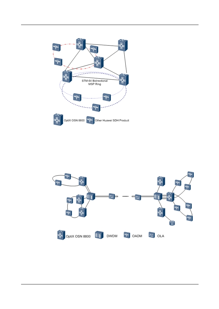
Figure 3-13 Network of the OptiX OSN 8800 combined with the OptiX OSN product
3.3.4 Networking with DWDM Equipment to Be the Supertrunk
Backbone Node
The OptiX OSN 8800 can work with the OptiX BWS 1600 to increase the regenerator-free span-
crossing distance.
Figure 3-14 Networking application of the OptiX OSN 8800 and the DWDM equipment
25